FlashBastd
New member
December 2008
Hi, just got around to fitting the external temp sensor and posh clock, here is what I did;
The parts you need are;
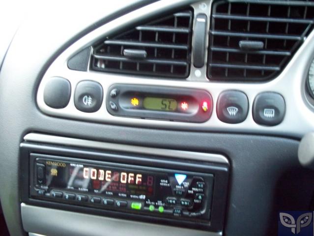
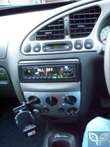
Fiesta Ghia X clock, with temp function
Ford temp probe (high spec Granada / Scorpio / Focus / Mondeo Mk1 & 2, all Mondeo Mk3, or the Fiesta the clock came out of), ideally with as long of a length of wiring beyond the plug as possible, and the clip to mount the plug.
Approx 5m twin core cable
Computer audio connector
Length of wire coathanger
Black duct tape
Torx screwdrivers
10mm socket
Crimp connectors
Computer audio connection (see below)
Cable ties
Preparation;
Remove the stereo and pop out your existing clock, you will notice that the plug is quite chunky. Remove the white plastic cover from the back of your new clock and enlarge the hole, a dremmel is ideal, but I did it with a stanley knife and pair of wire cutters.
Connect the 5m of cable to the temp sensor, I used crimp connectors and wrapped up the wiring with insulating tape.
When you look at the connectors on the back of the new clock, you will see there are 6 pins together as per your existing clock, and two pins on their own for the temp sensor. What I did was take the new clock to Maplin and look for computer audio connections that looked as though they would fit. I bought three different ones, took them home, and as the first one fitted well, returned the others. As you only need the plug with a length of wire stemming from it, snip the plug from the other end.
Take your temp sensor and temporarily connect to the new clock and plug into the cars wiring to make sure it works, if it does - positive eBay feedback, if not, check your connections, then contact the seller.
Right, so we know it all works, connect time to fit it.
1. remove front numberplate

2. remove lower grille (tabs along the top and bottom, be careful, some will break)
3. Disconnect negative terminal of battery (10mm socket)
4. Open bonnet, remove top of airbox, disconnecting MAF from loom and ducting to throttle body
5. Remove upper grille (two torx)
6. Remove n/s headlamp (two torx and twist clip to inside front of headlamp to release rear catch.
7. Peel back rear insulating strip and remove engine bay fusebox lid (iirc 2 clips)
8. Unplug the two large plugs from the fusebox, this is only to make it a bit easier to get the temp sensor wiring through the grommet, along with the other wiring from the fusebox.
9. Release and open the wiring loom holder from the n/s of the engine bay - towards the rear of the engine bay this is held in place by a tie wrap with a push clip on it. If you are careful, you can snip a bit out and re-fit later with some more conventional tie wrap.
10. Remove and disconnect stereo
11. Remove and disconnect old clock
12. Peel back door rubber on n/s door to allow the carpet to be folded back, providing access to the kick panel area
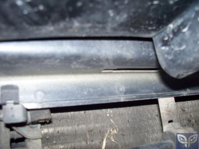
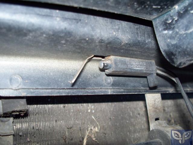
13. mount temp sensor, if you look behind the bumper to the o/s of where the numberplate mounts you will see a rectangular slot, this is the OE location for the temp sensor. I mounted the sensor here then clipped the sensor plug to the lower edge of the slam panel.
14. run the wiring up to the top of the panel behind the bumper and then through the space in the panel to the headlamp area.
15. the wiring for the headlamp and MAF runs through a tidy cover. Undo the clip and one end and the tape at the other, and fix the wiring inside it, before replacing the clip and using the duct tape to re-fix the other end of the cost.
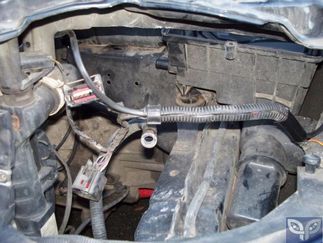
16. the wiring then runs up the inside of the wing, through a wiring cover, run the new wiring through this, then into the upper fusebox from the left hand end, where you will see an opening.
17. check and secure your wiring so far with tie wraps, at this stage you can refit the wiring cover along the side of the engine bay.
18. take the coathanger, straighten it, and using the duct tape fix the end of the wire to it. Make sure the end isn't sharp, using the duct tape to blunt / soften it to avoid damaging the existing wiring.
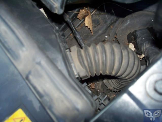
19. using the coathanger, ease the wiring down through the grommet into the cabin of the car.
20. reach up behind the edge of the glovebox and hopefully find the wiring. Remove the duct tape and extract the coathanger. Pull through any excess wiring.
21. you should have plenty of wire in the cabin now, so it is as good a time as any to connect the plug to the wiring.
22. route the wiring to the back of the clock area, connect to the new clock and connect the car loom to the clock. You can refit the clock now, but don't refit the stereo until we know it works.
23. refit airbox, connect ducting to MAF, reconnect loom to MAF
24. replace headlamp, don't forget to plug it in. Remember, two torx AND the twist clip.
25. reconnect the two large plugs in the engine bay fusebox, replace fusebox lid and the rubber sealing strip.
26. reconnect the battery
27. check that the temp clock works as it did when you initially checked it prior to installation.
28. refit stereo
29. set clock, stereo settings
30. refit grilles & numberplate
and I think that is about it!
part no's:
temp sensing clock - 1011837 - £96.35
temp sensor - 6820218 - £50.93
Hi, just got around to fitting the external temp sensor and posh clock, here is what I did;
The parts you need are;
Fiesta Ghia X clock, with temp function
Ford temp probe (high spec Granada / Scorpio / Focus / Mondeo Mk1 & 2, all Mondeo Mk3, or the Fiesta the clock came out of), ideally with as long of a length of wiring beyond the plug as possible, and the clip to mount the plug.
Approx 5m twin core cable
Computer audio connector
Length of wire coathanger
Black duct tape
Torx screwdrivers
10mm socket
Crimp connectors
Computer audio connection (see below)
Cable ties
Preparation;
Remove the stereo and pop out your existing clock, you will notice that the plug is quite chunky. Remove the white plastic cover from the back of your new clock and enlarge the hole, a dremmel is ideal, but I did it with a stanley knife and pair of wire cutters.
Connect the 5m of cable to the temp sensor, I used crimp connectors and wrapped up the wiring with insulating tape.
When you look at the connectors on the back of the new clock, you will see there are 6 pins together as per your existing clock, and two pins on their own for the temp sensor. What I did was take the new clock to Maplin and look for computer audio connections that looked as though they would fit. I bought three different ones, took them home, and as the first one fitted well, returned the others. As you only need the plug with a length of wire stemming from it, snip the plug from the other end.
Take your temp sensor and temporarily connect to the new clock and plug into the cars wiring to make sure it works, if it does - positive eBay feedback, if not, check your connections, then contact the seller.
Right, so we know it all works, connect time to fit it.
1. remove front numberplate
2. remove lower grille (tabs along the top and bottom, be careful, some will break)
3. Disconnect negative terminal of battery (10mm socket)
4. Open bonnet, remove top of airbox, disconnecting MAF from loom and ducting to throttle body
5. Remove upper grille (two torx)
6. Remove n/s headlamp (two torx and twist clip to inside front of headlamp to release rear catch.
7. Peel back rear insulating strip and remove engine bay fusebox lid (iirc 2 clips)
8. Unplug the two large plugs from the fusebox, this is only to make it a bit easier to get the temp sensor wiring through the grommet, along with the other wiring from the fusebox.
9. Release and open the wiring loom holder from the n/s of the engine bay - towards the rear of the engine bay this is held in place by a tie wrap with a push clip on it. If you are careful, you can snip a bit out and re-fit later with some more conventional tie wrap.
10. Remove and disconnect stereo
11. Remove and disconnect old clock
12. Peel back door rubber on n/s door to allow the carpet to be folded back, providing access to the kick panel area
13. mount temp sensor, if you look behind the bumper to the o/s of where the numberplate mounts you will see a rectangular slot, this is the OE location for the temp sensor. I mounted the sensor here then clipped the sensor plug to the lower edge of the slam panel.
14. run the wiring up to the top of the panel behind the bumper and then through the space in the panel to the headlamp area.
15. the wiring for the headlamp and MAF runs through a tidy cover. Undo the clip and one end and the tape at the other, and fix the wiring inside it, before replacing the clip and using the duct tape to re-fix the other end of the cost.
16. the wiring then runs up the inside of the wing, through a wiring cover, run the new wiring through this, then into the upper fusebox from the left hand end, where you will see an opening.
17. check and secure your wiring so far with tie wraps, at this stage you can refit the wiring cover along the side of the engine bay.
18. take the coathanger, straighten it, and using the duct tape fix the end of the wire to it. Make sure the end isn't sharp, using the duct tape to blunt / soften it to avoid damaging the existing wiring.
19. using the coathanger, ease the wiring down through the grommet into the cabin of the car.
20. reach up behind the edge of the glovebox and hopefully find the wiring. Remove the duct tape and extract the coathanger. Pull through any excess wiring.
21. you should have plenty of wire in the cabin now, so it is as good a time as any to connect the plug to the wiring.
22. route the wiring to the back of the clock area, connect to the new clock and connect the car loom to the clock. You can refit the clock now, but don't refit the stereo until we know it works.
23. refit airbox, connect ducting to MAF, reconnect loom to MAF
24. replace headlamp, don't forget to plug it in. Remember, two torx AND the twist clip.
25. reconnect the two large plugs in the engine bay fusebox, replace fusebox lid and the rubber sealing strip.
26. reconnect the battery
27. check that the temp clock works as it did when you initially checked it prior to installation.
28. refit stereo
29. set clock, stereo settings
30. refit grilles & numberplate
and I think that is about it!
part no's:
temp sensing clock - 1011837 - £96.35
temp sensor - 6820218 - £50.93
")