Mod's perhaps we could pin and lock this as a "How To"
Thanx Dave
Those of you following my project will know I have been having grief with the Engine Temp Gauge, because my Puma is a "Digital Dash" model and the ECU I'm using doesn't support an output suitable to operate the gauge like the original 1.7 Puma ECU did.
You should know by now that I like everything to work as it should, so bunging an aftermarket gauge somewhere just isn't an option for me I'm afraid.
This will also apply to guys running more Standard Puma's with aftermarket ECU's and also perhaps conversions on other vehicles could be done in a similair way
Here Goes...................
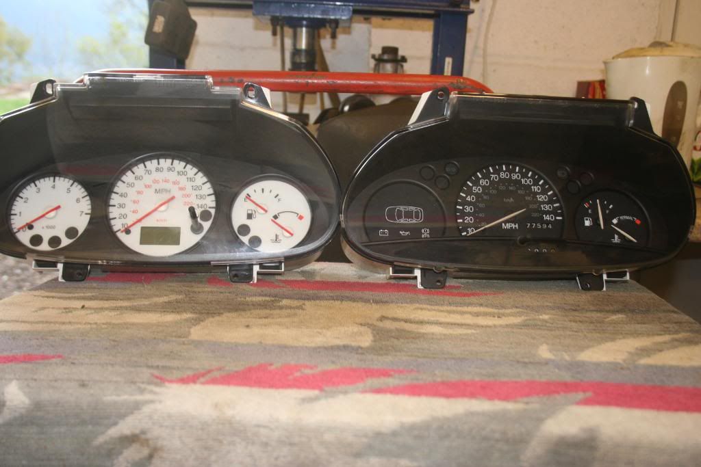
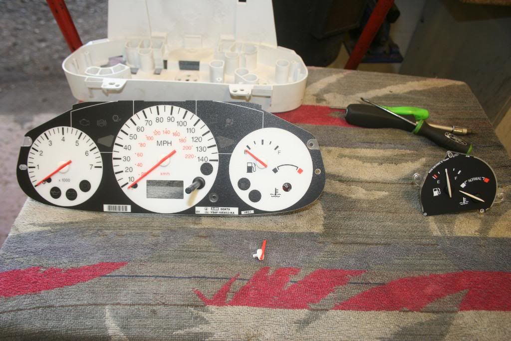
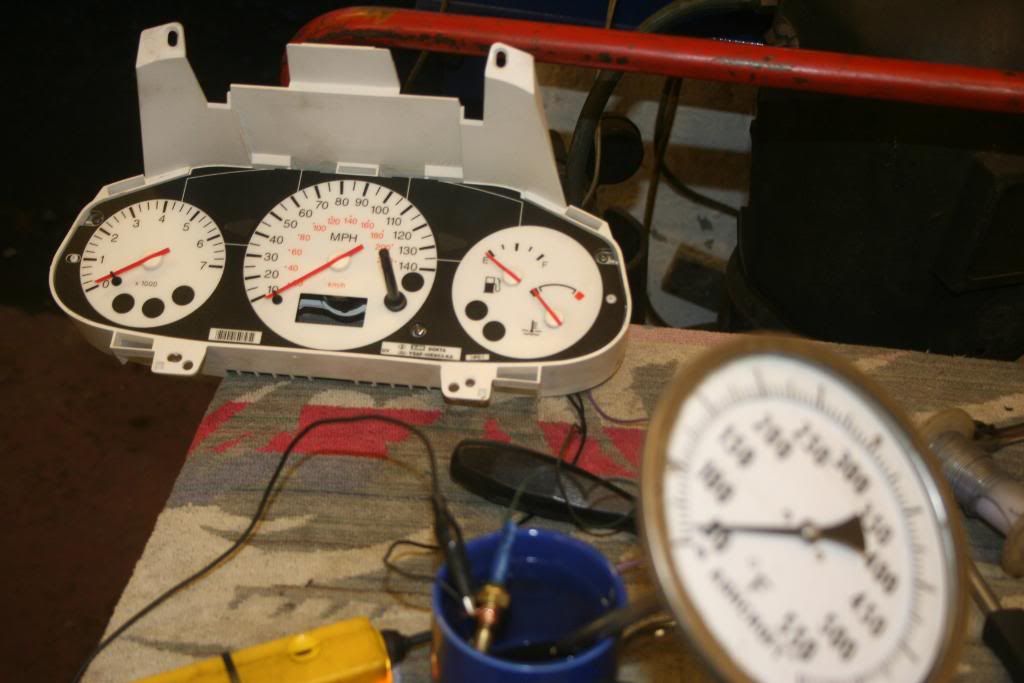
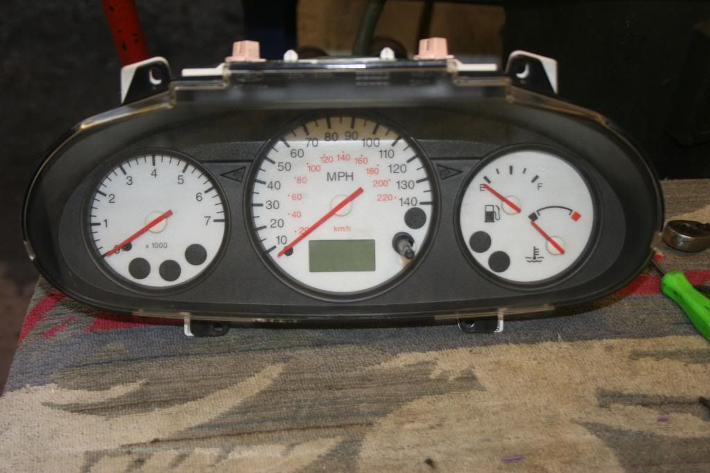
Puma Dash Set on the left, MkIV Fiesta on the right, (MkIV Fiesta's use a more convenional "Analogue Type Gauge")................
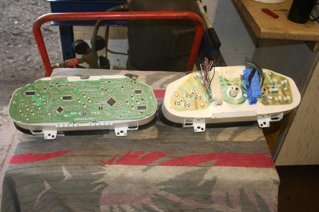
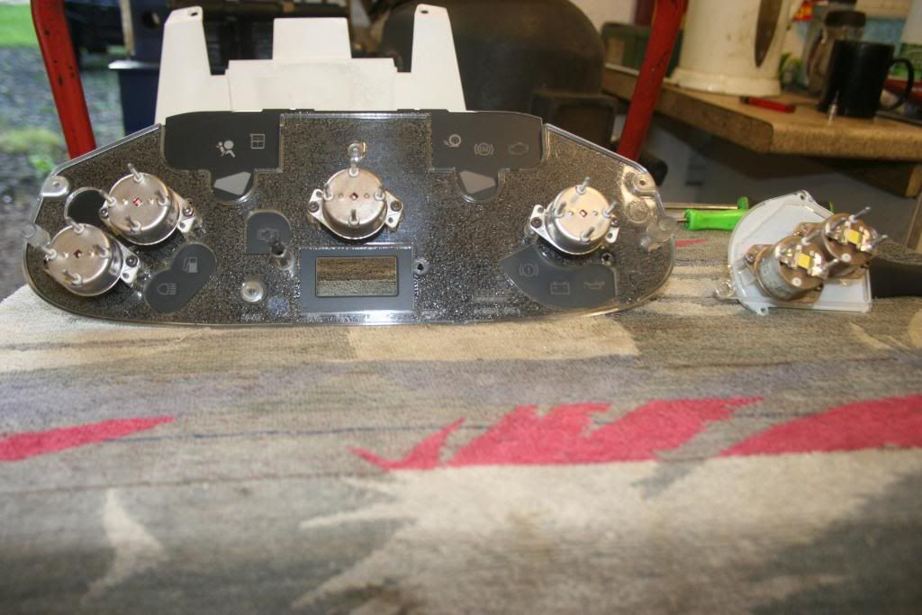
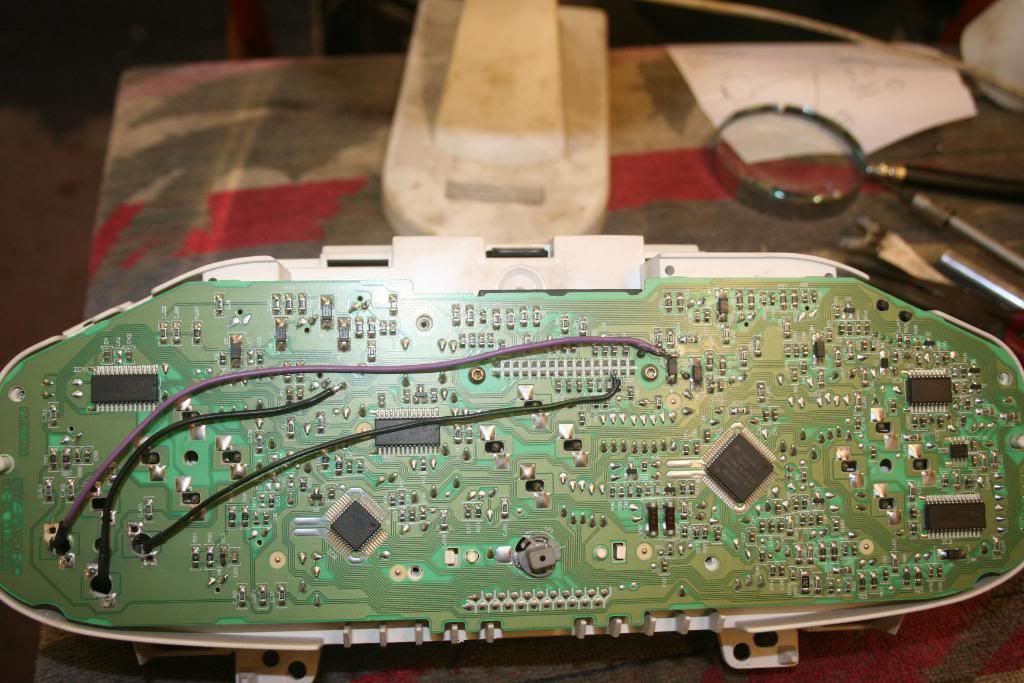
And the back view...............
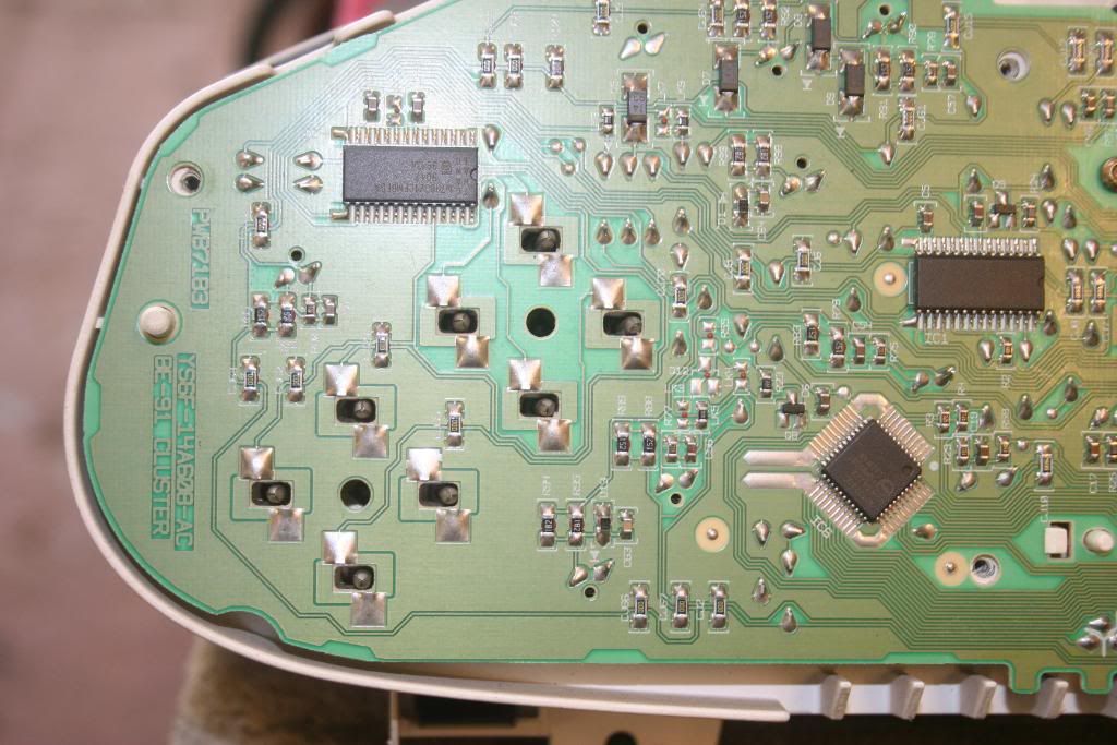
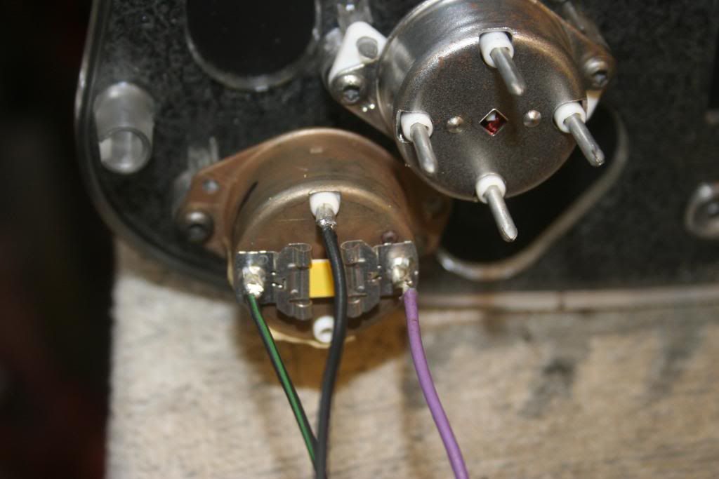
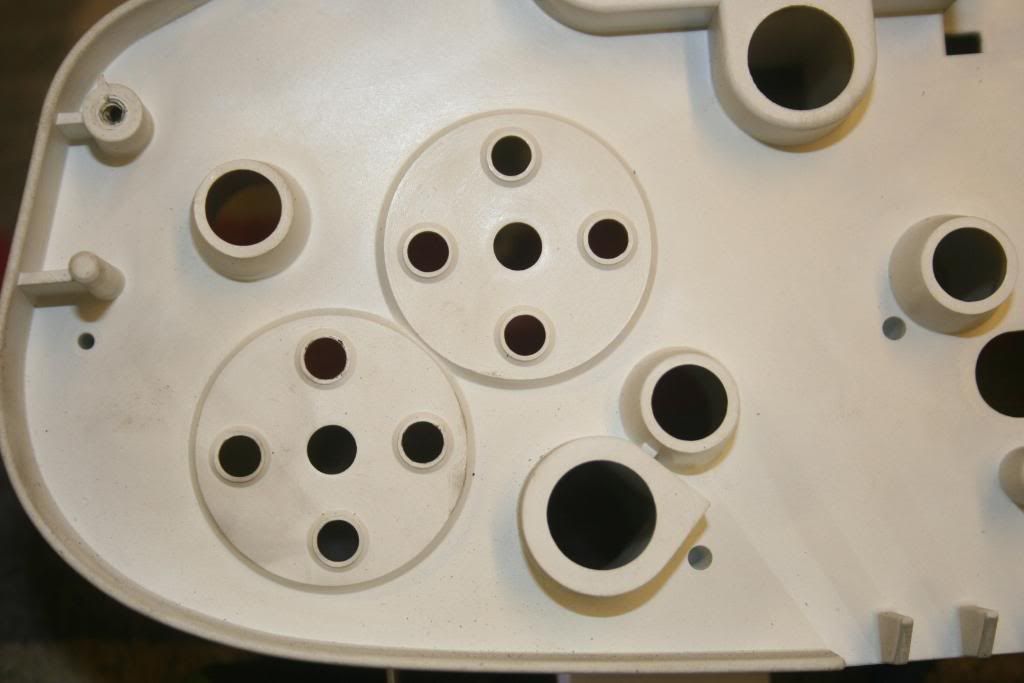
Close up of Puma temp gauge connections (note 4 pins, controlled by chip set)................
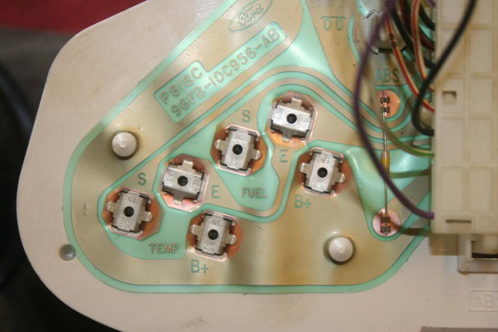
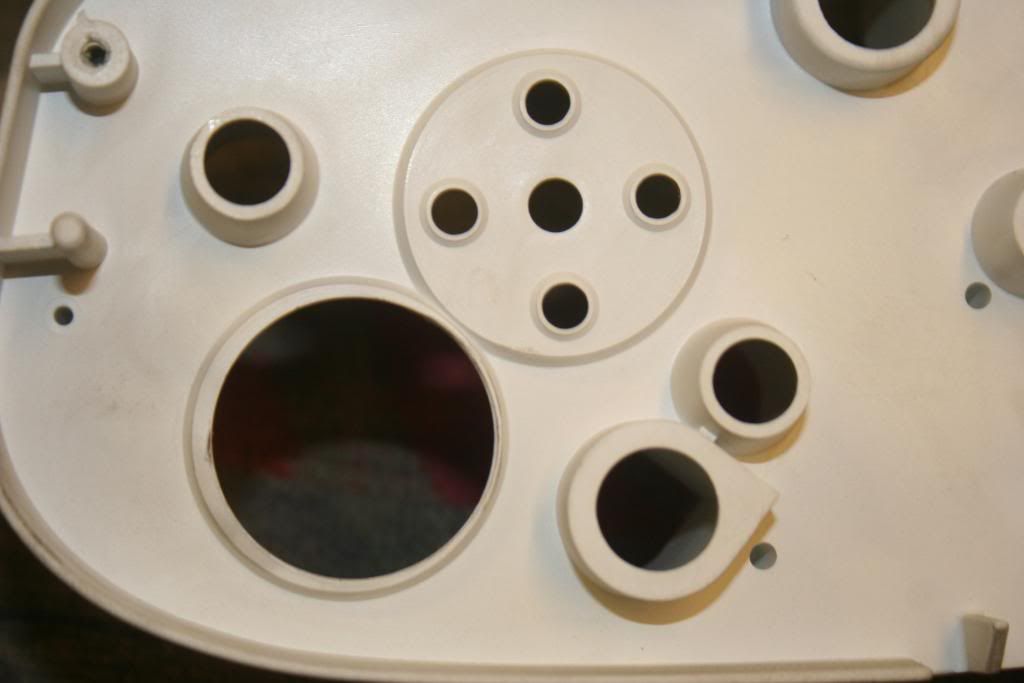
Close up of Fiesta, (3 connections), using convenional type sender unit, and even conveniently labelled Battery + / Earth / and Sender by Uncle Henry's Boyz ..................
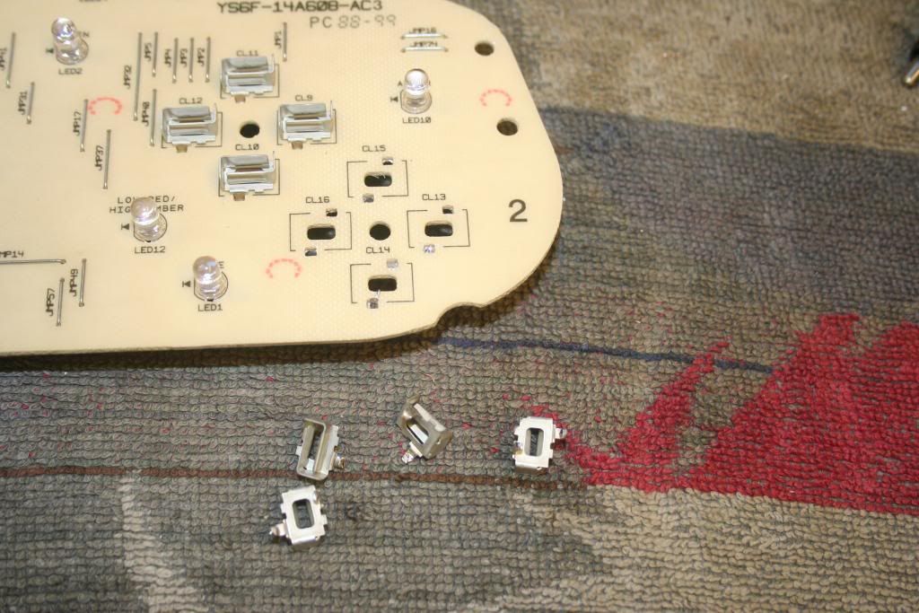
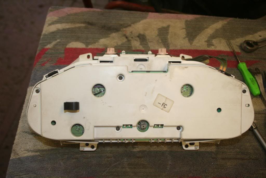
Next picture shows clock sets stripped down to relevant bits for surgery, note the needle carefully removed from the Puma gauge with a modified "fork" to pop it upward and off without bending 'owt ...............
And the back view...............
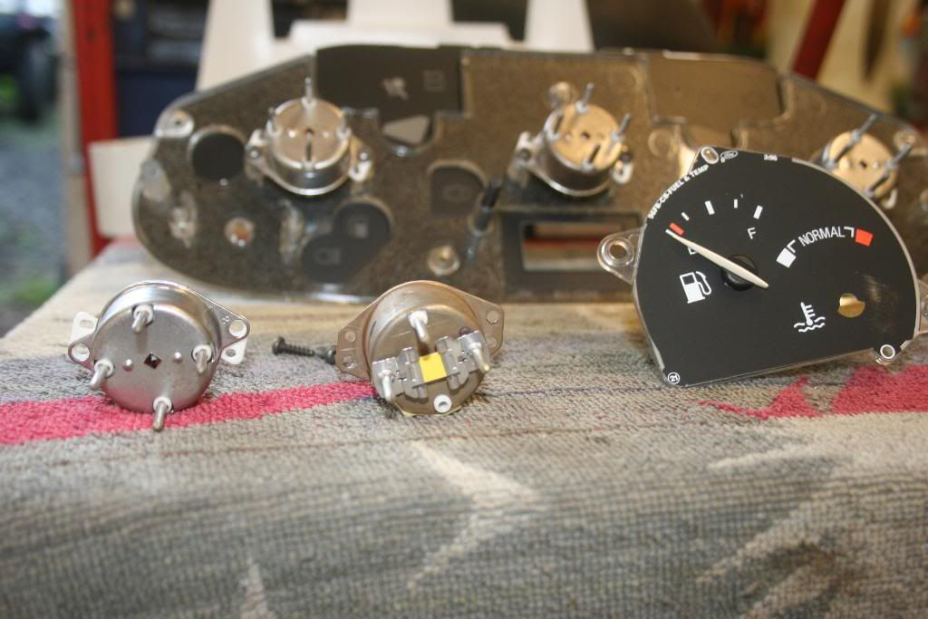
Gauge units now removed and side by side, Puma on left Fiesta on right.
It was at this point I realised how easy this was going to be, good old Fords, that's why I love modding them................If you look carefully even the screw holes are in the same place ..............
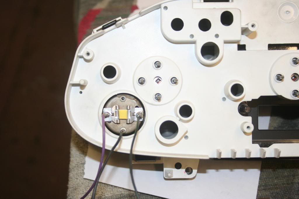
Fiesta gauge unit screwed into Puma face panel, (in actual fact I mounted this the other way up for final assembly as it was easier to enlarge the other 3 holes in the PCB later on) I've snipped the pins shorter, and soldered on 3 bits of thin wire using Ford Colours:- Purple Ign +, Black Earth and Black & Green Sender. I also slipped a bit of heat shrink over the wires / pins to prevent the possibility of them touching the holes on the PCB ............
Next job, de solder the 4 pin connectors from the Puma PCB, then I drilled the holes out a little bigger in the PCB to allow good clearance on the wires.
Go easy here, don't make 'em too big or you may break into another track and bugger the PCB
The Fiesta gauge unit is slightly deeper than the Puma one so will foul on the back of the housing here....................
2 seconds with a hole cutter, et voila ..............
I then stuck the gauge unit back into the housing and connected up the 3 wires temporarily to test it so far.
Essential Tip !! ..........Before you fit the needle you have to put 12 V on the Ign + and Earth, which sets the gauge into its "powered up" rest position, while the 12V is applied push the needle down so it is just on the start of the black sector.
When you remove power the needle will drop a gnats todger to the stop in the dial face
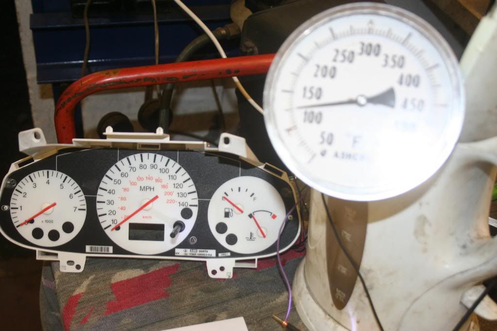
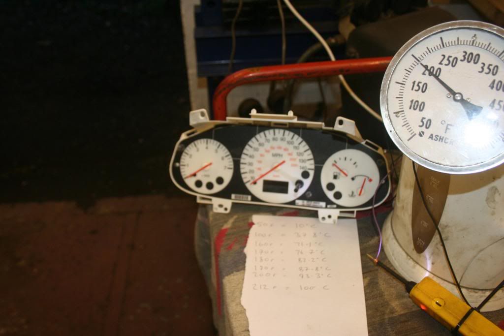
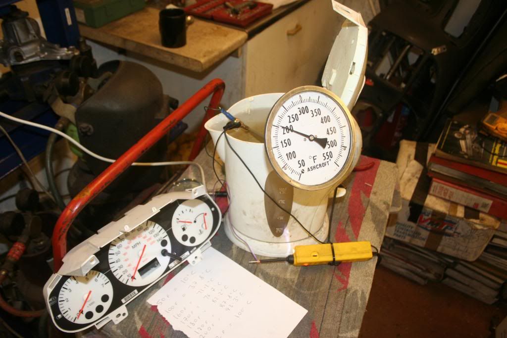
Here it is, needle installed, wired temporary, with sender in a cup of room temperature water ...................
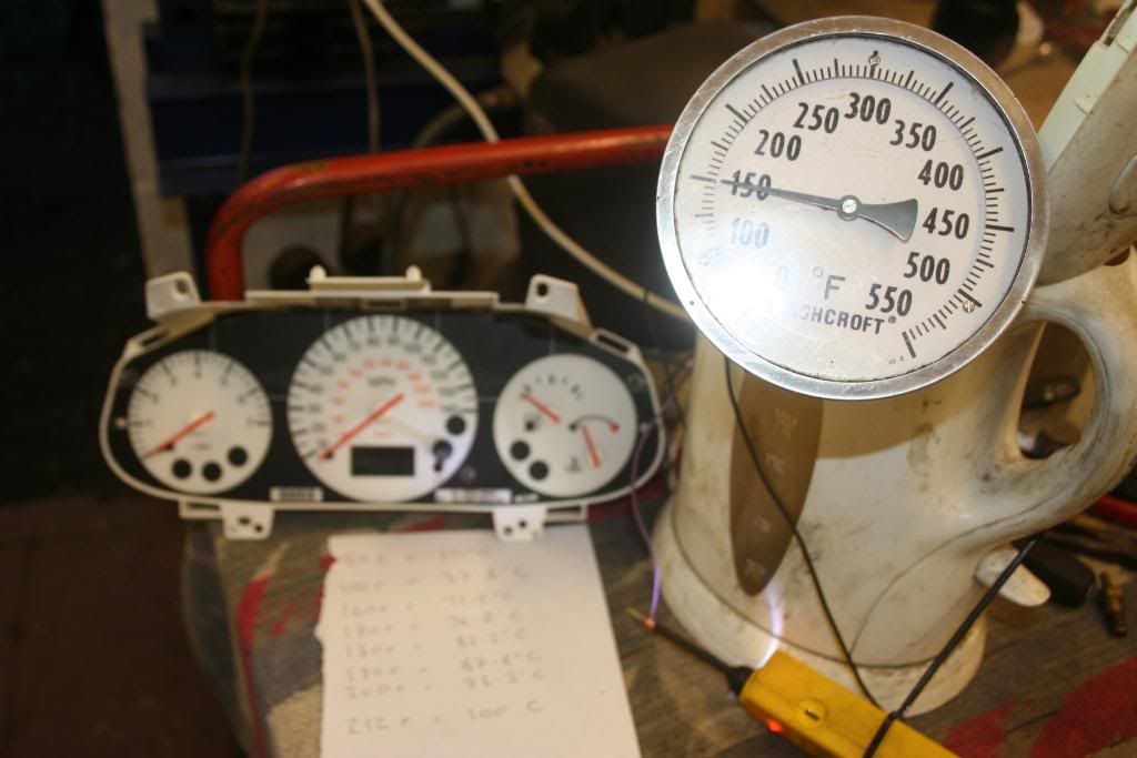
Now wanna know how accurate it is, get yr kettle out, and with an accurate thermometer and sender inserted in a kettle of water, switch on the kettle and compare gauge readings to accurate thermometer
Note, most engines run between 75 to 88 Celcius (about 165 to 190 F) A "Hot" engine will be 200 F and above, , (water boils at 212 F) ...........
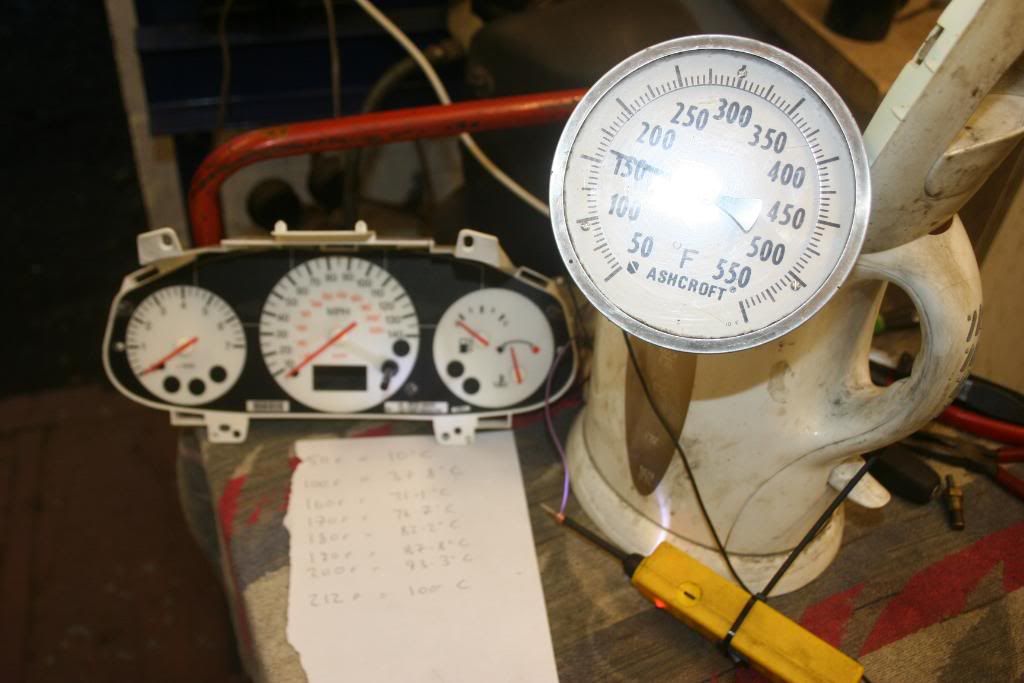
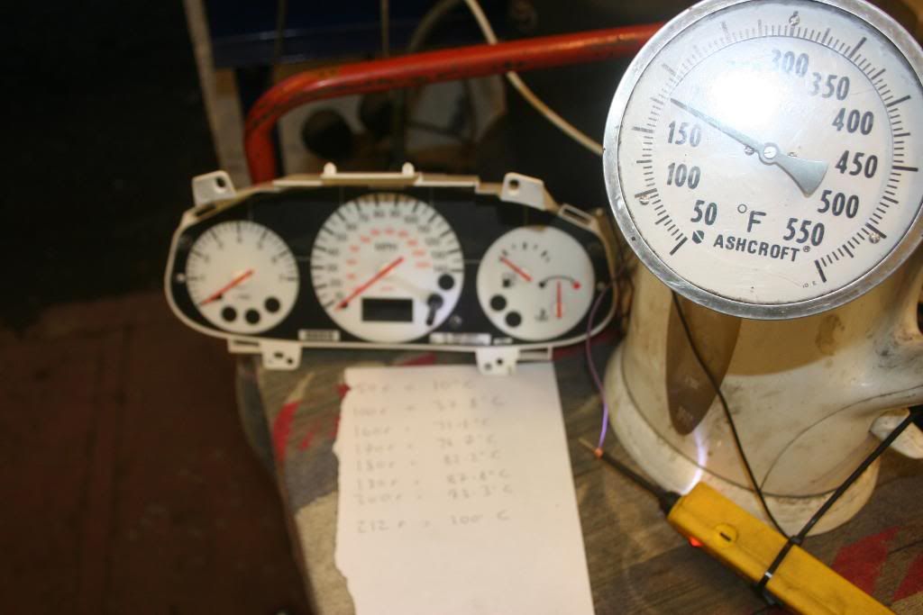
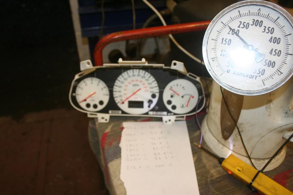
and with water just about to boil, it's just off the red (remember water is pressurised in an engine, so gauge will be in red sector just before the engine boils .............
I'm well happy with that, so time to wire it up properly, view so far from the back
Now at this point I could have fitted the PCB and all the covers back on and hooked the wires into the cars wiring at the Dash Cluster Plug
But weeeee don't wanna do that, oh no, no, no, lets do it properly and solder the wires onto the PCB, very fiddly but a much nicer way of doing it ...................
And here's the last 2 views back and front, only a very trained eye would ever know I'd been in there fiddling .................
I've plugged it into the car, it is all working fine including all other gauges and warning lights..................
Jobbie Jobbed
Cheers Dave
Thanx Dave
Those of you following my project will know I have been having grief with the Engine Temp Gauge, because my Puma is a "Digital Dash" model and the ECU I'm using doesn't support an output suitable to operate the gauge like the original 1.7 Puma ECU did.
You should know by now that I like everything to work as it should, so bunging an aftermarket gauge somewhere just isn't an option for me I'm afraid.
This will also apply to guys running more Standard Puma's with aftermarket ECU's and also perhaps conversions on other vehicles could be done in a similair way
Here Goes...................
Puma Dash Set on the left, MkIV Fiesta on the right, (MkIV Fiesta's use a more convenional "Analogue Type Gauge")................
And the back view...............
Close up of Puma temp gauge connections (note 4 pins, controlled by chip set)................
Close up of Fiesta, (3 connections), using convenional type sender unit, and even conveniently labelled Battery + / Earth / and Sender by Uncle Henry's Boyz ..................
Next picture shows clock sets stripped down to relevant bits for surgery, note the needle carefully removed from the Puma gauge with a modified "fork" to pop it upward and off without bending 'owt ...............
And the back view...............
Gauge units now removed and side by side, Puma on left Fiesta on right.
It was at this point I realised how easy this was going to be, good old Fords, that's why I love modding them................If you look carefully even the screw holes are in the same place ..............
Fiesta gauge unit screwed into Puma face panel, (in actual fact I mounted this the other way up for final assembly as it was easier to enlarge the other 3 holes in the PCB later on) I've snipped the pins shorter, and soldered on 3 bits of thin wire using Ford Colours:- Purple Ign +, Black Earth and Black & Green Sender. I also slipped a bit of heat shrink over the wires / pins to prevent the possibility of them touching the holes on the PCB ............
Next job, de solder the 4 pin connectors from the Puma PCB, then I drilled the holes out a little bigger in the PCB to allow good clearance on the wires.
Go easy here, don't make 'em too big or you may break into another track and bugger the PCB
The Fiesta gauge unit is slightly deeper than the Puma one so will foul on the back of the housing here....................
2 seconds with a hole cutter, et voila ..............
I then stuck the gauge unit back into the housing and connected up the 3 wires temporarily to test it so far.
Essential Tip !! ..........Before you fit the needle you have to put 12 V on the Ign + and Earth, which sets the gauge into its "powered up" rest position, while the 12V is applied push the needle down so it is just on the start of the black sector.
When you remove power the needle will drop a gnats todger to the stop in the dial face
Here it is, needle installed, wired temporary, with sender in a cup of room temperature water ...................
Now wanna know how accurate it is, get yr kettle out, and with an accurate thermometer and sender inserted in a kettle of water, switch on the kettle and compare gauge readings to accurate thermometer
Note, most engines run between 75 to 88 Celcius (about 165 to 190 F) A "Hot" engine will be 200 F and above, , (water boils at 212 F) ...........
and with water just about to boil, it's just off the red (remember water is pressurised in an engine, so gauge will be in red sector just before the engine boils .............
I'm well happy with that, so time to wire it up properly, view so far from the back
Now at this point I could have fitted the PCB and all the covers back on and hooked the wires into the cars wiring at the Dash Cluster Plug
But weeeee don't wanna do that, oh no, no, no, lets do it properly and solder the wires onto the PCB, very fiddly but a much nicer way of doing it ...................
And here's the last 2 views back and front, only a very trained eye would ever know I'd been in there fiddling .................
I've plugged it into the car, it is all working fine including all other gauges and warning lights..................
Jobbie Jobbed
Cheers Dave
")