My puma cossie - few bits and bobs. (Very picture heavy!)

ProjectPuma

Help Support ProjectPuma:

This site may earn a commission from merchant affiliate links, including eBay, Amazon, and others.
The TCS switch is actually for antilag. looks better than a fog light logo anyway!!

Well decided to have a mess with the wiring. Started making my fuel pump loom ready for the 044 pump. Just need to get the fitting kit and measure the loom up in place on the car as the tank is further back than on a standard car. Also currently my fuel pump loom although well clipped up is not far from exhaust and totally exposed to elements etc so it is being relocated so that the wiring comes out of boot floor via a gromit directly on top of the fuel tank, that way its all protected and has a short run. This is it so far:

DSC00051.jpg


Need to do some measuring then fit a relay connector. Im using the original fuel pump power feed as the trigger for the relay in the boot and the power and earth is being taken direct from the boot (boot mounted battery!) so i get a good stable supply.

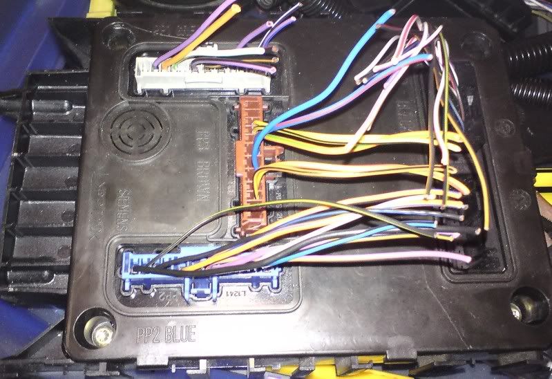
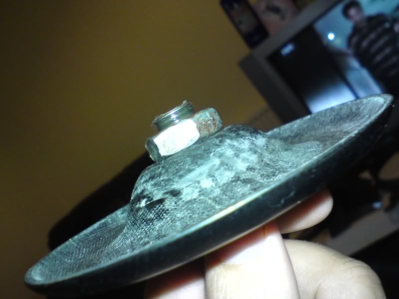
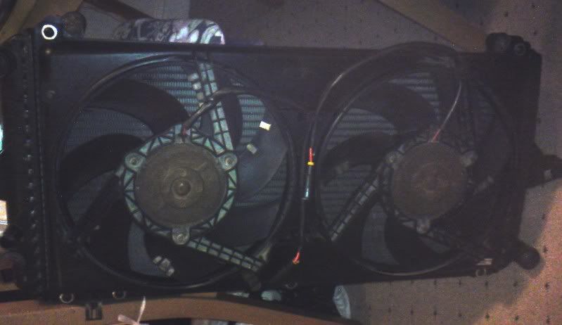
Set about pulling apart the engine bay wiring today as i need a new header tank cap as my old one leaks and my fans keep blowing the fuse so i cant really drive it unless i rely on the "backup" radiator fans commonly known as the heater fans :cry:

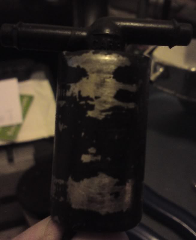
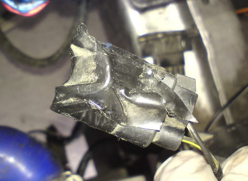
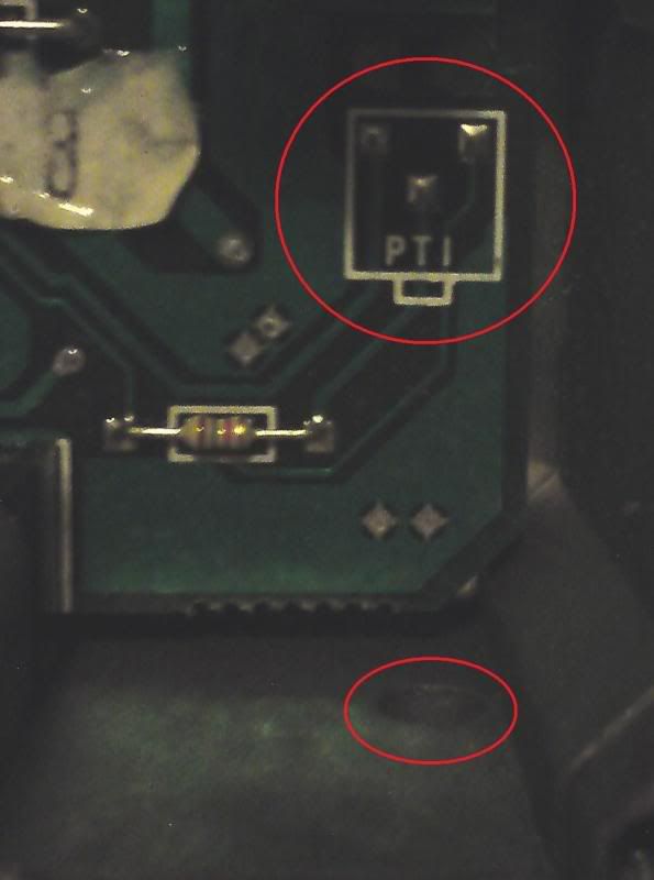
Firstly i removed this stupid air bypass valve thingy that wasnt even connected:
DSC00050.jpg

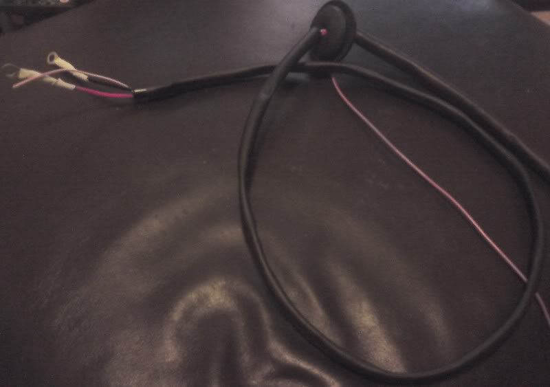
It was fed by its own relay and fuse taken off the battery junction box and triggered by an ignition live and switch next to my antilag switch. Removed it all!!

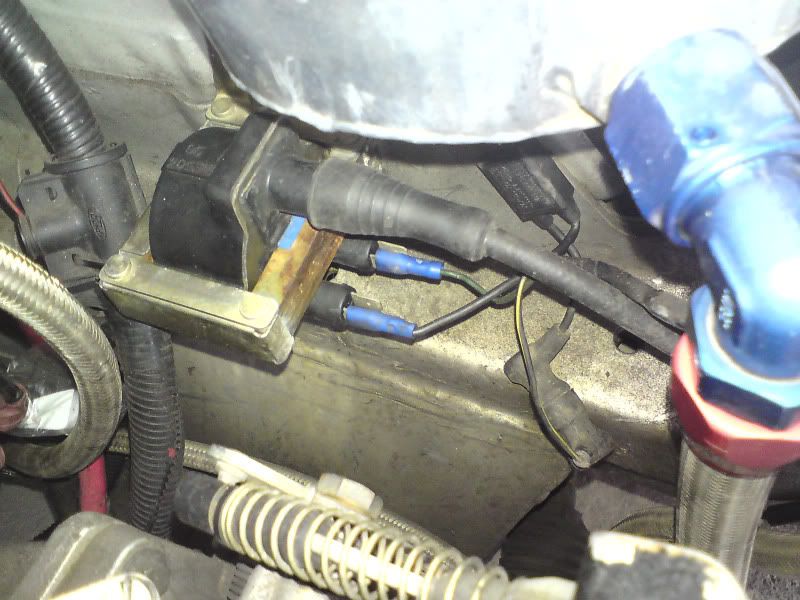
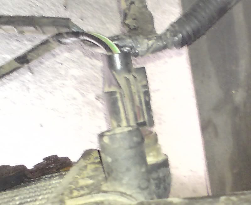
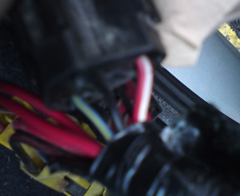
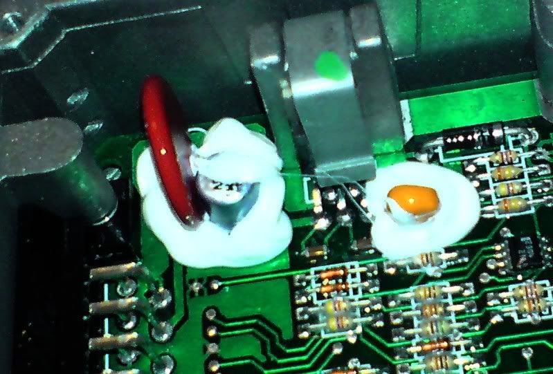
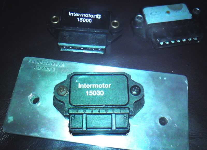
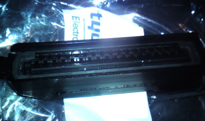
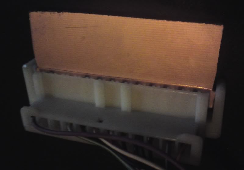
I then took a look at the wiring near the coil to try and find the lecktron valve connector.
DSC00032_2.jpg

Found i have a group A coil apparently because of the connector on it.
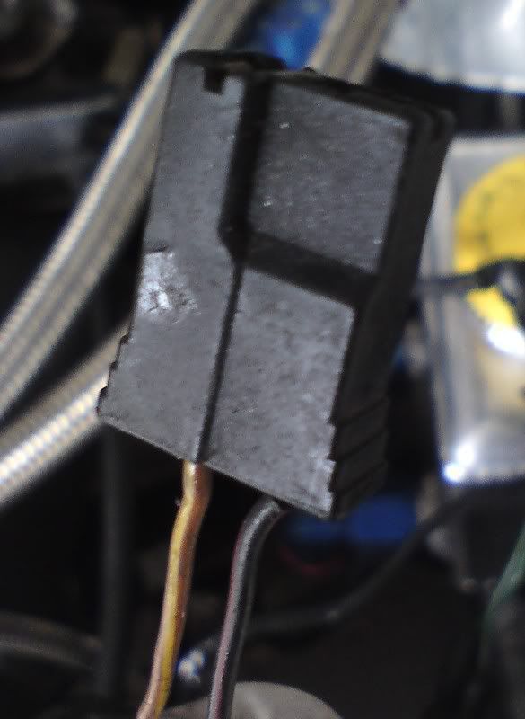
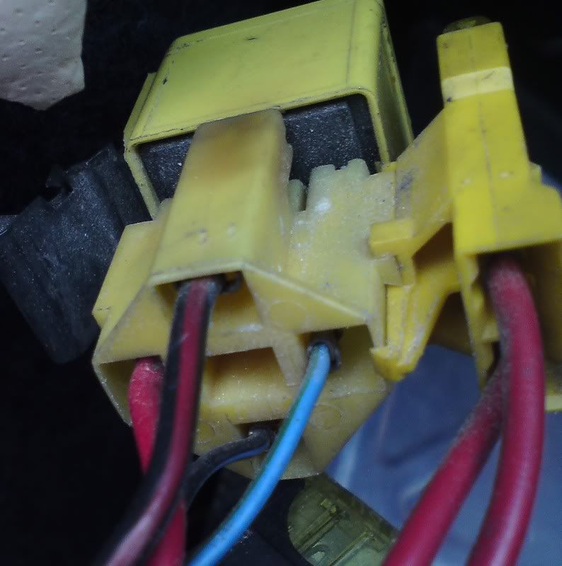
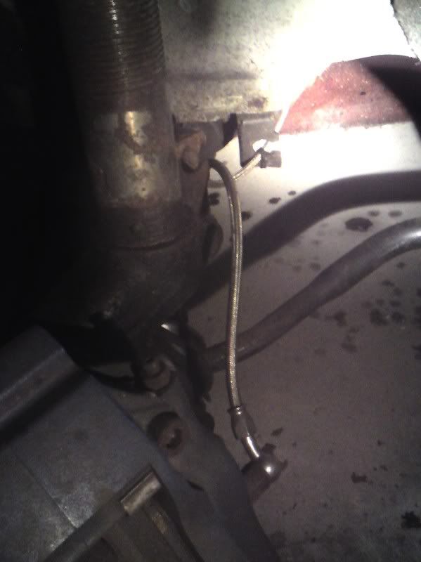
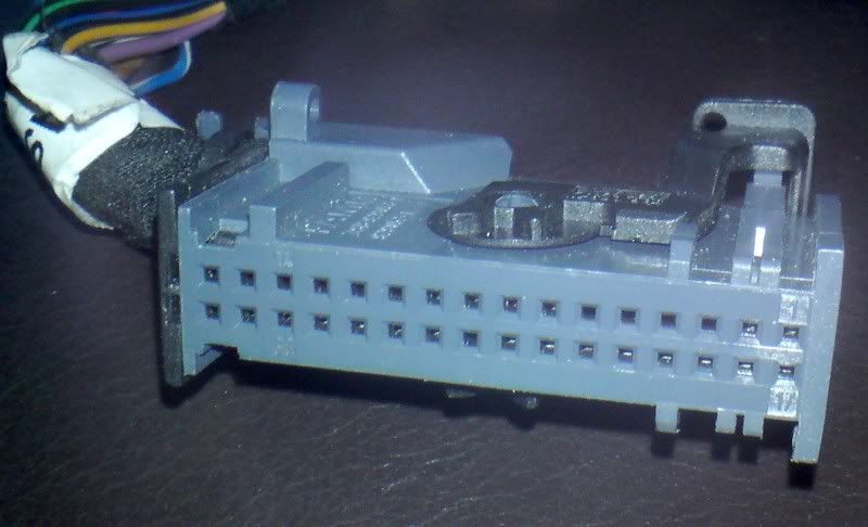
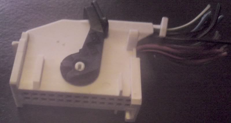
I have found all taped up what i believe to be the amal valve connection:
DSC00036.jpg

So a bit of repair and that shall be set up ready for fitting a new chip and a lecktron valve.
I also found another bodge!! The alarm sensor on the bonnet is defective, yet the alarm doesnt sound the fault signal!! this is the sensor plug and he had bodged it with a bit of wire so the alarm doesnt detect the fault. Left it under the tape as it works for now until i get the new bonnet sensor.
DSC00043.jpg


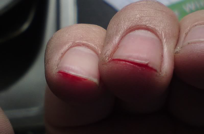
Oh on a side note, be careful when using your nails to pick connectors open:
DSC00038_2.jpg

Yes that hurt!!

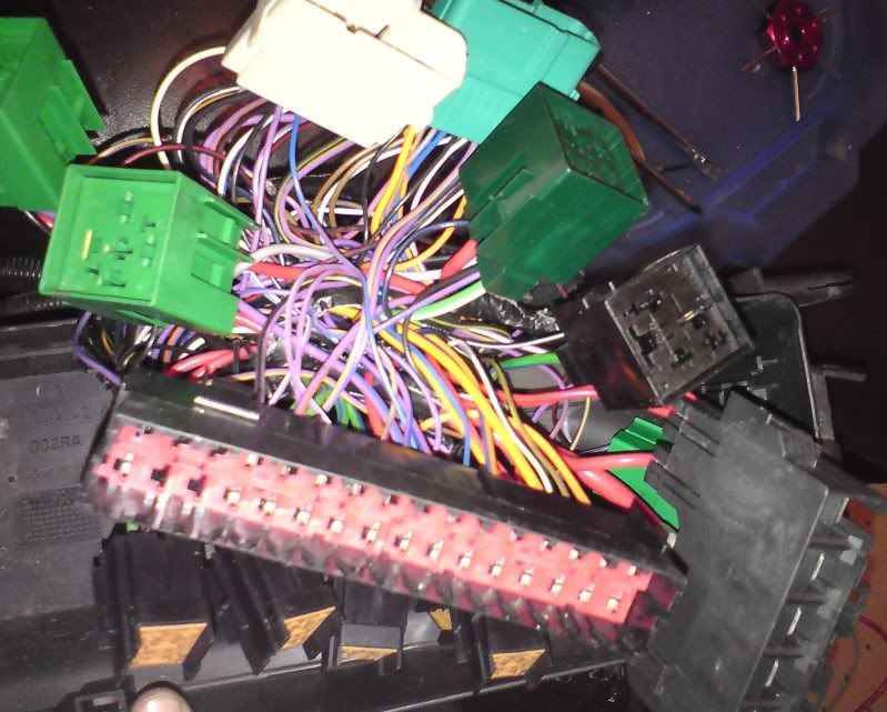
Ive also started to trace the fan wiring so i can rip it out for new. So far its all wrapped with the rest of the car loom so going to take a while to unravel and find the relay etc. Was looking at the fan switch on the radiator and im a bit confused:
DSC00042.jpg


The circular connector only has two wires which seems wrong to me. Surely there should be 4 wires, 2 for each fan stage, ie supply in and feed to fan for each fan. the earth i have found so thats solved. Anyone know why only 2 wires??

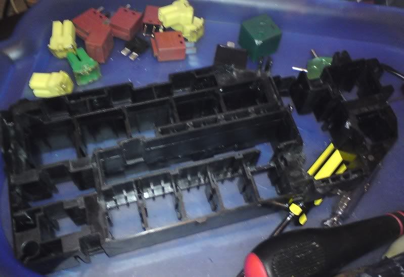
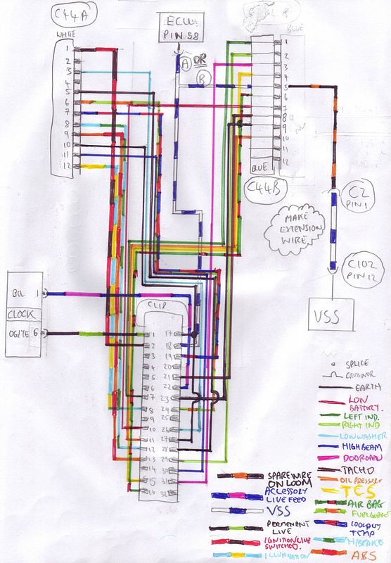
Ive been told my loom is a saphire 4x4 engine loom which in theory makes it easier as at least i know what im looking at. Ive had a look at the two main engine loom relays and arent sure which one is which.
DSC00044.jpg

DSC00045.jpg

If i can find a saphire wiring diagram i can identify each one by the colours of the wires.

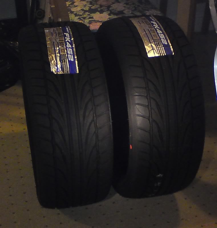
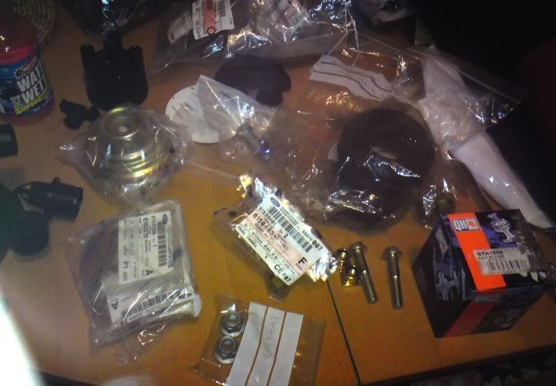
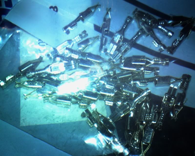
Also these arrived in the post today:
DSC00048.jpg

Just need to get them fitted!!! Local garage wanted £130 PER tyre fitted!! Camskill came up £128 the pair delivered!!! :'(
 
Started to pull apart a spare fusebox i had. The original puma has a two stage fan system with a low speed and high speed relays feeding one fan via a resister, all fed by a 60A fused supply.

Now thats ideal to be modified for my needs. I wont be using a resister as i have two fans and the switch is on the radiator not ECU controlled, BUT it means i have 2 spare relay positions in my fusebox with all the right supplys for a new fan wiring installation!

Luckily for me, most modern fords use a easy to dismantle modular fuse box. All the relay holders unclip for easy maintenance and repair (yet ford claims it will only supply a full loom - so why design it modular and repairable then? go figure!).

All the connectors disconnected from the fuse box:
DSC00053.jpg


Looks a mess but its all colour coded, even the relays match colour of relay holder so you cant mix things up!!!

And this is where it all fits:
DSC00054.jpg


I only need to remove two relay holders and thier wiring from the loom so the spare connectors will be cut off and kept for recycling and any future repairs.

I also finished my wiring plans for the later "3 button" remote alarm. In essence all ive had to do is match the new pin to the equivilent old pin, no complex rewiring as such. So ive aquired the right connectors for the new alarm box:
DSC00055_2.jpg


Just need to raid the scrappy for an old style remote central locking box as i need to cut off the connectors on the box so i can link them to the new alarm and have the unit able to directly plug into the loom in my car. I intend to make it so its "plug and play" with no major butchery of the loom.
 
Carbontec have ceased trading after a fire destroyed thier factory and all the moulds.

Finally a short update!!

Cleaned my wheels properly today!! Nothing like a good soak to get them clean!!
DSC00335_2.jpg


Will do a proper update later this week as ive been busy doing a few bits and bobs trying to get it ready for ford fair after my suspension broke!!
 
Just a couple of pics really!

My front suspension strut died a while back!!

DSC00115.jpg

DSC00114.jpg

DSC00125.jpg


whoops!! the whole bearing and top cup is knackered so replacing it with new!!! The damper is being rebuilt with a new central rod to sort out the snapped one and im rebuilding the other side with new bearing etc just to be safe!!

Nice table of new bits and bobs to sort things out!!
DSC00344_2.jpg


Reassembled my rad and some escos fans i picked up ready to go back in:
DSC00345.jpg


This is the coilover i need to de-rust before taping the threads up.

DSC00343.jpg

I shall also sort out the springs!!

need to find a rubber grommit to go on this brake pipe clip:
DSC00338_2.jpg

A cable tie is just asking for chaffing damage!!! There isnt any damage so far but theres the potential so it needs sorting for piece of mind.
 
I thought id add a bit about the engine management. The engine management is pre EECV which a normal puma has and is an off the shelf "Magneti Marelli webber P8" management system that was made by Pectel (now PI) and being an off the shelf unit has a LOT of extra functions available to it that were not used on fords at all in some cases, and only activated for motorsport cars in other uses.

The basic printed circuit board is similar in concept to the earlier cosworth ECU's and even uses the same outer casing as the "level 8" ecu which was its predecessor. It has more memory than its predecessor as well as the ability to run closed loop control, coil packs all from the factory.

It also has an add on board that carrys extra memory and for motorsport can be swapped for "pectel board" or similar which can encode the Chip data as well as add extra functions such as antilag etc. It also enables datastreaming externally to monitoring systems subject to them being able to read the pectel "protocol" (in theory similar to the way a more modern ECU can be monitored).

As it stands i have a early collins copy of a pectel board but not sure which version it is.

I know my chip has to go as its a terry drury chip which is a rallycross map for a restricted rally engine using air injectors - and my car has no restrictor and is a road car! whoops

To aid identification i pulled ECU out car for a nosey (cars broken).

Removing the cover:
DSC00119_2.jpg

WTF bits of foam!!

Under the foam there is yellow tape:
DSC00118_2.jpg


And under the tape you can see the chip. note theres no manufacturer sticker etc like other tuners do to identify the product! As i understand it, the red paint is what terry drury did on his products.
DSC00117_2.jpg


Nothing under the board to help me either:
DSC00116.jpg


It does have "P8" written on it in two places but thats it.

Also on the main ECU circuit board there are these big blobs of white stuff:
DSC00120_2.jpg

Nothing is wrong there it just looks very odd!!

I wonder if the circuit board used in other cars/had later revisions???

I notice theres a lot of unused componant pads and tracks on the circuit board:
DSC00127.jpg

And this is where there is sometimes a CO adjustment screw!!
DSC00128.jpg
 
Thought id do an update for today!!! :lol:

Had to buy a few bits for preventative maintenance and tidying things up!!


DSC00364_2.jpg

First of all a massive bottle of kurust!! Will be spraying it liberally on the chassis and underbody while cars in the air to hold rust at bay until the winter when i can do a proper clean up of the underside.

Got myself some nice nimbus heat shield at coombe which is going to go round the turbo and downpipe area for shielding!!
DSC00363.jpg


Hopefully it will look something like this:
DSC02117.jpg

And it will then protect the brake system!

Ive got some new inlet manifold gaskets:
DSC00362_2.jpg

I need these as one of the securing bolts was missing on my car and the gasket is slightly displaced albiet not leaking with bolt replaced, should be changed to be on the safe side.

Ive also got some spare ignition amplifiers:
DSC00361.jpg

I need 2 to go coilpack but also wanted the backing plate so i can mount the second amplifier.

Got a bag of P clips off a mate in the right size for my fuel hoses so i can secure them a bit better as i feel the clip spacing is a bit too much at present in places!
DSC00360_2.jpg


Ive also been aquiring wiring loom bits so i can make my engine wiring loom:
DSC00359_2.jpg

and also a brand new ECU plug and terminals:
DSC00357_2.jpg

DSC00358.jpg
 
just....WOW. The amount of work and dedication in this car is stunning, Im very impressed. And I love that bonnet, it looks bad ass!
 
lots of work, but def be worth it once its all done, and u take that first drive!
 
While im sorting out various bits and bobs ive decided to start my digital dash wiring plans. Ive had to put my "3 button remote" conversion on hold as im struggling to find a second hand mk4 fiesta/early puma alarm module as my local scrappys only seem to have base spec fiestas with no alarm system!!!!:bat:

anyhow.... i have aquired a digital dash from a late puma:
DSC00453_2.jpg

And the connector with it:
DSC00447_2.jpg


I also want to try and fit this:
DSC00454.jpg

An ST170 focus dash!! Same level of technology and uses same kind of data inputs as the puma digital dash so i should be able to make it function. Primarily want it for the 160mph clocks and the fact its different!! Also going to rewire the dash illumination to utilise the dash dimmer switch from the focus.

Looking at the focus plug:
DSC00445.jpg

its simple computer pins and socket technology in the connectors so easy to connect up once ive done the wiring diagrams i need.

Ive got some pin strips for the loom:
DSC00444_2.jpg

and some connectors for the plugs:
DSC00446.jpg
 
Looking good, as said the amount of work you're putting into it is unreal! When are you hoping to get it on the road?
 
Looks great. Less impressed with the original electronics though. Is the yellow electricians' tape basically holding that chip in place?
 
The tape just covers the silicon chip itself up.

Well i been working out some of the wiring for my dash.

This is the 2 connectors on my current loom:
DSC00462_2.jpg

DSC00463-1.jpg

I have worked out all the pin functions and stuff i need to transfer accross and labelled each function.

Ive then done the same on the puma digital dash plug:
DSC00464.jpg

Labelling all the functions then transferring across functions i already have on analog loom so i know which pin to connect to which and where new wires need to be made into my loom.

Ive done the same on the focus plug:
DSC00465-1.jpg


Next step is to turn them into loom plans and get some spare connectors to hack up!!!
 
Well ive finally finished the wiring diagram to run a puma digital dash in an analogue car!! So just the loom to make, then send it to a guinea pig with an early car to test it (my car doesnt have speed sensor as standard and i dont want to fit a part if there's fundamental flaws with my plans, where as a normal car theres no permenant changes).

first of all i need to make a plug to go into analogue loom plugs. These are not available as they are an integrated part of the dash clocks so ive made my own using 2 sided copper clad board.

First i cut rough shapes then filed them down to fit:
DSC00485_2.jpg


Then tweaked them to fit the connectors:
DSC00486_2.jpg


The next stage is to separate the individual pins which i can do with a cutting wheel on my dremel (the quick easy way :lol:) or by buying etch resist pen and acid etching the board, proper PCB style like i was taught years ago!!! Not made my mind up yet!!! I might just use cutting wheel for the prototype and if its something people want me to make for thier cars then i might then do it properly!!!

This is the wiring diagram!
digidashtoanalogloom.jpg


Also been checking a few bits and bobs ready for MoT and getting the car back on the road.
 

Latest posts

Back
Top