As promised, I did the boot release modification and took some photos while doing it to make it easier for someone who got a bit puzzled just reading about it in how-to!
First thing is to go to your boot. After removing the rear trim I found this connector. The orange-brown wire is signalling the boot release mechanism. It gets its signal either form the button in the rear light, or (in case you have a three button key) from the interior i.e. when signalled with the (ignition) key
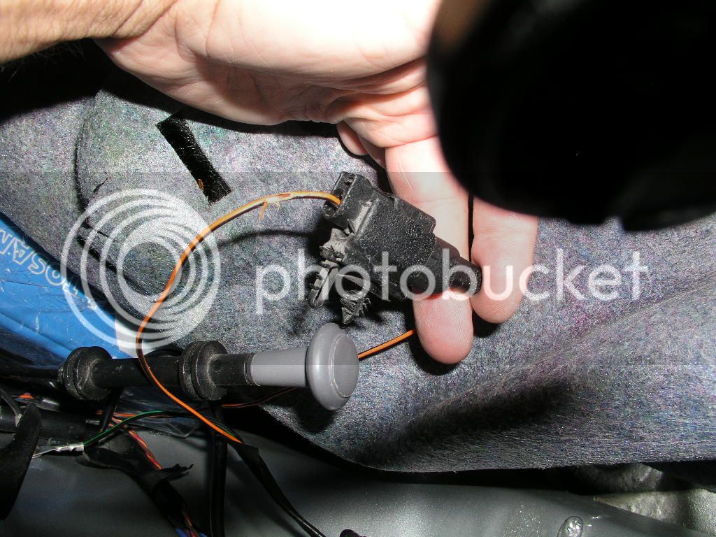
Now, the how-to suggests to cut it and leave it be. I had a challenge on that: why lose some of functionality if it is ALREADY built in?
So I just skinned the wire a bit and soldered another wire to it. This way you get the best of both worlds: the boot can be opened from outside (when engine is not running), you keep the remote key funcionality plus you get the ability to open it from cabine while the engine is running.
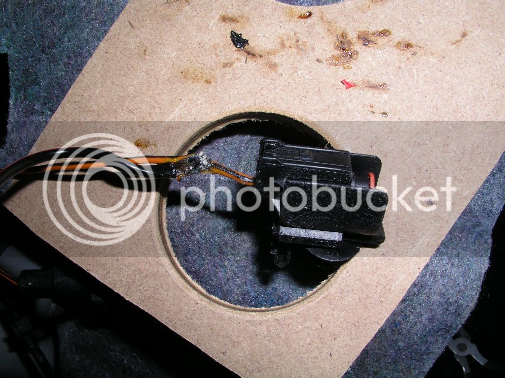
I just skinned the wire, didn't cut it. It was a mistake; now I strongly recommend to cut it and then resolder it together. That way you can use heatshrink insulation, conditio sine qua non to longetivity and tidy electrical instalation(s)! Anyway, my car is RHD vehicle and this connector is in the left rear corner of a car; I have no idea where it is for the UK cars, but you can see how it looks and it is presumably also in boot!
Ok, once soldered, the single wire is routed to the front of a car and the connector reconnected. This wire will be connected to a permanent live 12V via the ka boot release switch. When you press it it connects the 12V to the rear motor releasing the boot door.
This was easy, let's turn our attention to the front now.
The switch has 7 pins, but we will need only 4 of them.
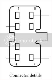
(disclaimer: this image is taken from Fordwiki.co.uk; I hope they wouldn't mind!)
The pins 4 and 5 are used for light of switch during night. You will need to find two wires that are switchable courtesy of the main stalk. As I have there the regulator for the mainlights levelling, I used them!
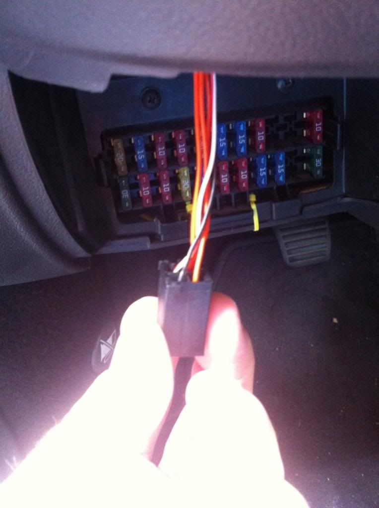
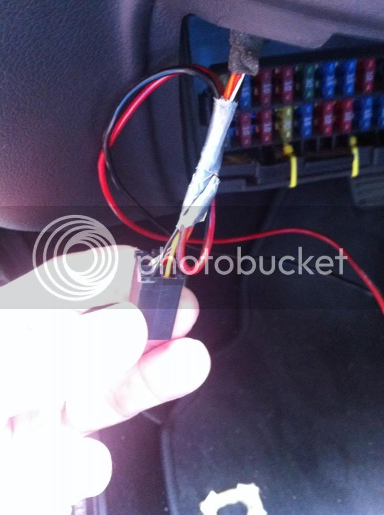
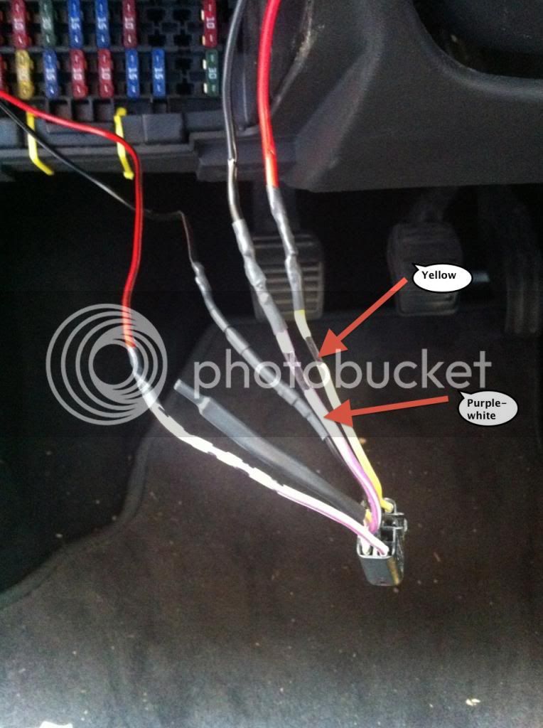
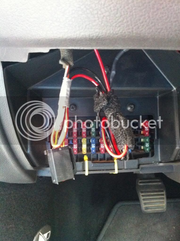
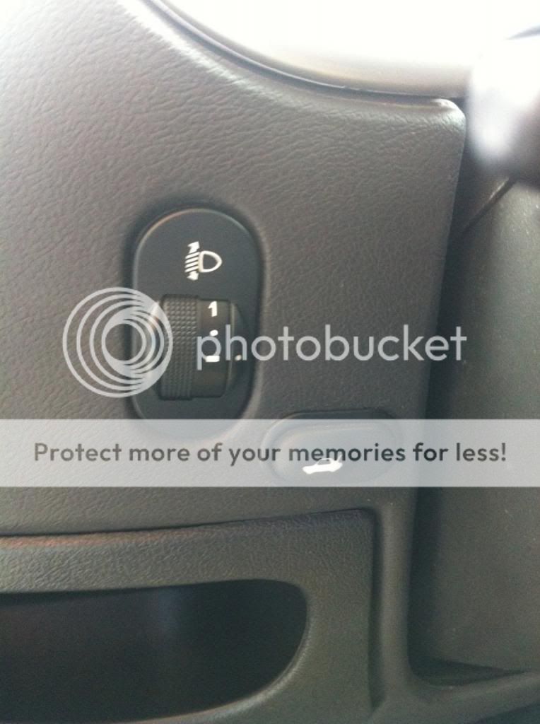
When you take down the safety fuses cover you can pop out the switch for mainlights levelling. When you do it and disconnect the plugin, you are left with four positions. The black one is ground (-12V); the orange one next to it is the 12V we want (switchable; when you switch on the lights it gets +12V and turns on the light for the switch). You have another pin used for another two orange wires which has the same function, but it is easier to work with just one wire!
So there you have it: the black one gets connected to the pin 4, the orange one to the pin 5.
All soldered and insulated, ready for the connecting the switch. This is not necessary if you don't want your switch to be lighted (I am not sure about this wording, I guess you understand what I wanted to say; please bear with me, English is not my mother's tongue!). Whatever you decide to do, it won't affect the basic funcionality of the system!
Enabling the funcionality of a switch. As I said, you have to connect live 12V to the switch for releasing the boot.
Poping out the radio and looking for the permanent +12V.
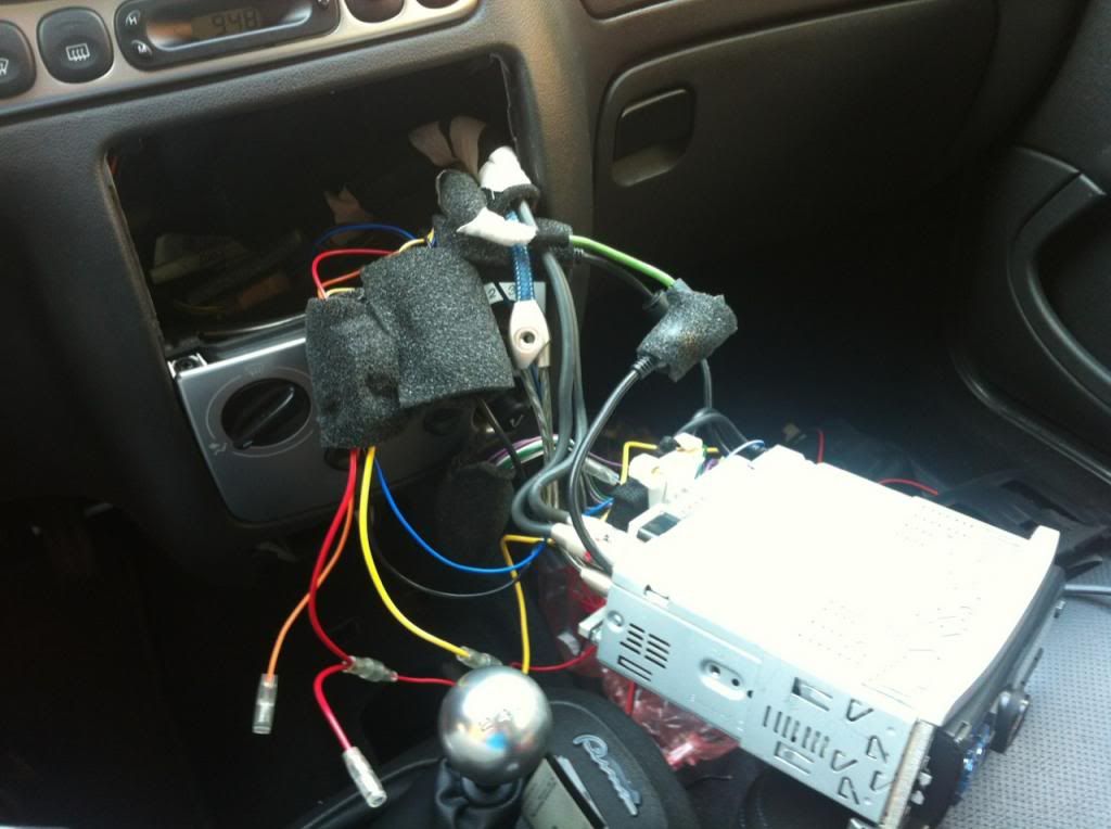
(As you can see, all the heavier items/wires have been taped over to minimise rattle and noise)
It is the red wire (small surprise!)
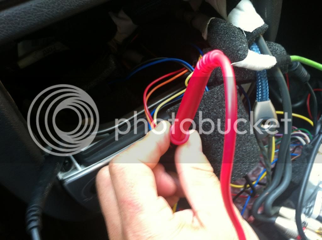
Now it would be VERY GOOD idea to disconnect the car battery as we are about to cut the red wire and then resolder it with another wire which will be connected to the switch!
Route the cable to the place where you want to put your switch and connect it the plugin. When I bought the switch it came without plugin. After looking around I found out that the lugin fir the electric opertion of windows on ka/puma/fiesta Mk4/5 is EXACTLY the same! I sourced one of them and adapted it. Only one pin had to be moved.
Now, the schmatics are as follows. The live +12V connect EITHER to the pin 2 or pin 7. It really doesn't matter, as you are connecting them together when you press the switch. To the other one you connect the wire you have routed form the boot and soldered to the brown-orange wire in the boot.
Before you close up everything with insulation, try out if it works. If everything was done correctly, you should be able to open boot with your switch, regardless if the engine is running or not (provided that you have connected the battery back!)!
I used heat shrink insulation for everything to make it nice, clean, safe and durable.
The surplus wire for the backlight of the switch is neatly taped together to avoid any strain on the connector
It is good idea to recheck everything works. That means you have to connect back the battery. As all the soldering has been done, and everything is insulated, nothing can go wrong!
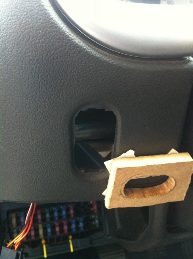
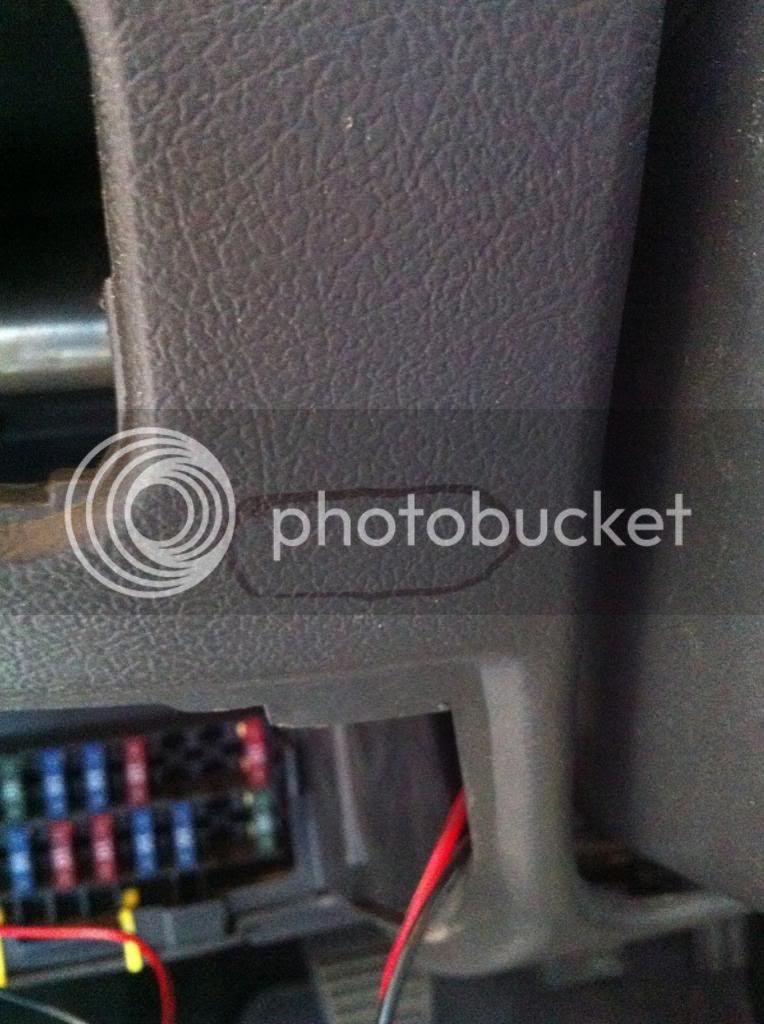
I decided to put my switch next to the light levelling switch. To make sure if fits nicely, but also to check the curvature of the dashboard I made a small pattern out of MDF. After making sure the switch fits in, I used the double sticking tape to stick it to the desired position. We are about to make a hole in the dashboard, and it is one-way ticket! No mistakes allowed here!
And there you have it! The interior boot release switch neatly installed, backlight operational, the boot can be opened from inside when the engine is running. From outside and by key only when the engine is not running; we kept the factory funcionality and safety and gave it an extra value of practicality!
First thing is to go to your boot. After removing the rear trim I found this connector. The orange-brown wire is signalling the boot release mechanism. It gets its signal either form the button in the rear light, or (in case you have a three button key) from the interior i.e. when signalled with the (ignition) key

Now, the how-to suggests to cut it and leave it be. I had a challenge on that: why lose some of functionality if it is ALREADY built in?
So I just skinned the wire a bit and soldered another wire to it. This way you get the best of both worlds: the boot can be opened from outside (when engine is not running), you keep the remote key funcionality plus you get the ability to open it from cabine while the engine is running.

I just skinned the wire, didn't cut it. It was a mistake; now I strongly recommend to cut it and then resolder it together. That way you can use heatshrink insulation, conditio sine qua non to longetivity and tidy electrical instalation(s)! Anyway, my car is RHD vehicle and this connector is in the left rear corner of a car; I have no idea where it is for the UK cars, but you can see how it looks and it is presumably also in boot!
Ok, once soldered, the single wire is routed to the front of a car and the connector reconnected. This wire will be connected to a permanent live 12V via the ka boot release switch. When you press it it connects the 12V to the rear motor releasing the boot door.
This was easy, let's turn our attention to the front now.
The switch has 7 pins, but we will need only 4 of them.

(disclaimer: this image is taken from Fordwiki.co.uk; I hope they wouldn't mind!)
The pins 4 and 5 are used for light of switch during night. You will need to find two wires that are switchable courtesy of the main stalk. As I have there the regulator for the mainlights levelling, I used them!

When you take down the safety fuses cover you can pop out the switch for mainlights levelling. When you do it and disconnect the plugin, you are left with four positions. The black one is ground (-12V); the orange one next to it is the 12V we want (switchable; when you switch on the lights it gets +12V and turns on the light for the switch). You have another pin used for another two orange wires which has the same function, but it is easier to work with just one wire!
So there you have it: the black one gets connected to the pin 4, the orange one to the pin 5.

All soldered and insulated, ready for the connecting the switch. This is not necessary if you don't want your switch to be lighted (I am not sure about this wording, I guess you understand what I wanted to say; please bear with me, English is not my mother's tongue!). Whatever you decide to do, it won't affect the basic funcionality of the system!
Enabling the funcionality of a switch. As I said, you have to connect live 12V to the switch for releasing the boot.
Poping out the radio and looking for the permanent +12V.

(As you can see, all the heavier items/wires have been taped over to minimise rattle and noise)
It is the red wire (small surprise!)


Now it would be VERY GOOD idea to disconnect the car battery as we are about to cut the red wire and then resolder it with another wire which will be connected to the switch!
Route the cable to the place where you want to put your switch and connect it the plugin. When I bought the switch it came without plugin. After looking around I found out that the lugin fir the electric opertion of windows on ka/puma/fiesta Mk4/5 is EXACTLY the same! I sourced one of them and adapted it. Only one pin had to be moved.
Now, the schmatics are as follows. The live +12V connect EITHER to the pin 2 or pin 7. It really doesn't matter, as you are connecting them together when you press the switch. To the other one you connect the wire you have routed form the boot and soldered to the brown-orange wire in the boot.
Before you close up everything with insulation, try out if it works. If everything was done correctly, you should be able to open boot with your switch, regardless if the engine is running or not (provided that you have connected the battery back!)!

I used heat shrink insulation for everything to make it nice, clean, safe and durable.
The surplus wire for the backlight of the switch is neatly taped together to avoid any strain on the connector

It is good idea to recheck everything works. That means you have to connect back the battery. As all the soldering has been done, and everything is insulated, nothing can go wrong!
I decided to put my switch next to the light levelling switch. To make sure if fits nicely, but also to check the curvature of the dashboard I made a small pattern out of MDF. After making sure the switch fits in, I used the double sticking tape to stick it to the desired position. We are about to make a hole in the dashboard, and it is one-way ticket! No mistakes allowed here!


And there you have it! The interior boot release switch neatly installed, backlight operational, the boot can be opened from inside when the engine is running. From outside and by key only when the engine is not running; we kept the factory funcionality and safety and gave it an extra value of practicality!

 ose:
ose: