Newbie Cheap Puma Project with custom intake manifold

ProjectPuma

Help Support ProjectPuma:

This site may earn a commission from merchant affiliate links, including eBay, Amazon, and others.

[email protected]

New member
Joined
May 1, 2012
Messages
89
Location
Blackpool
Hi all, I'm new to the site, thought I would start a thread of my girlfriends Puma (it is hopefully going to be mine soon with all the work i've done to it / she doesn't see much point running a 1.7 / I prefer it to my car lol)

9291f644.jpg


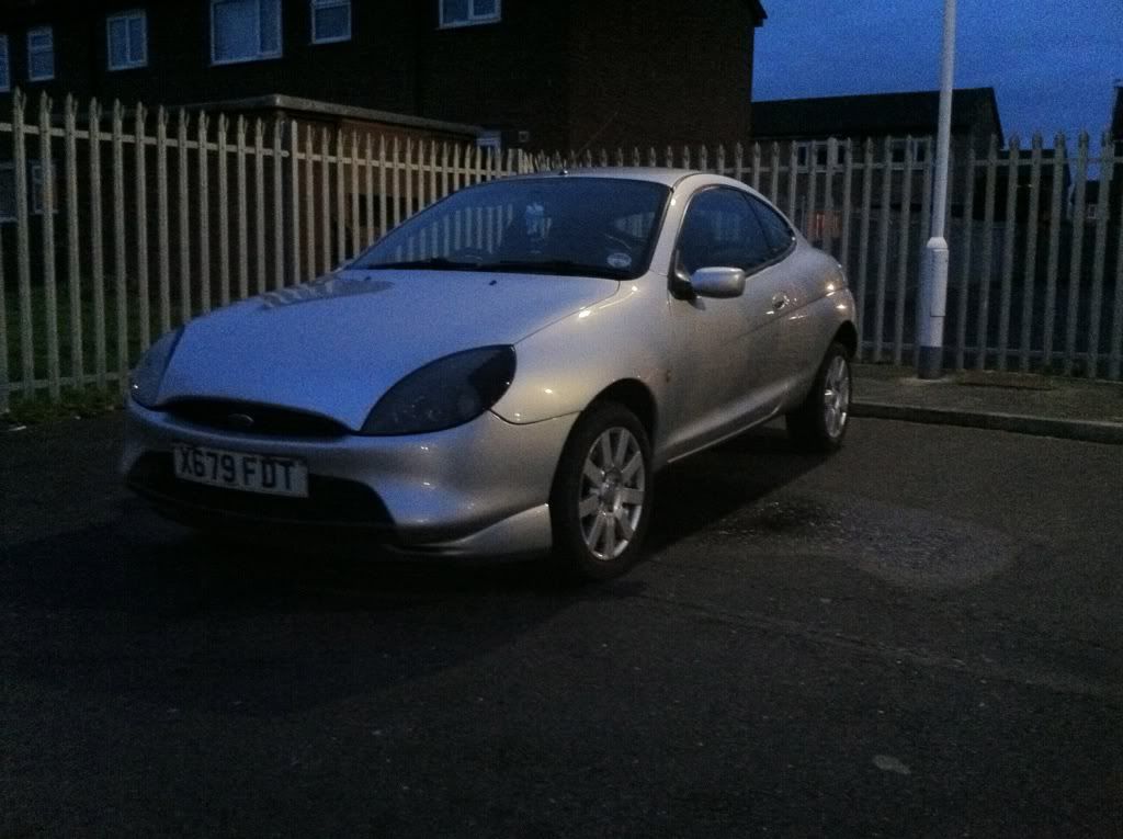
I Bought the car for £500, only had 78,000 on the clock with a long MOT (last year), was in very good condition but had bad rear arches (of course!) So... the work began! :roll:

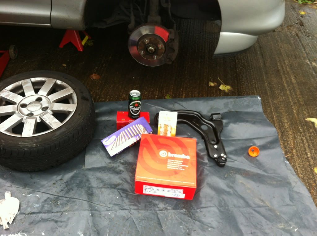
Firstly, the O/S bottom ball joint had worn so it was banging around, replaced it with a nice shiny new one, plus some standard part Brembo discs and pads, I also fitted myself with some lunch in the form of a sandwich and chocolate fingers washed down with a nice cold beer :) p.s. was Friday afternoon, not a midweek morning! :wink:

93af5f13.jpg


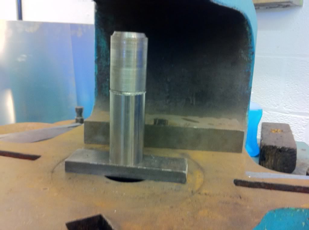
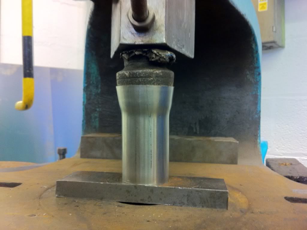
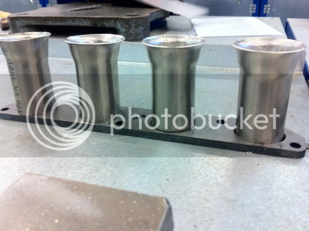
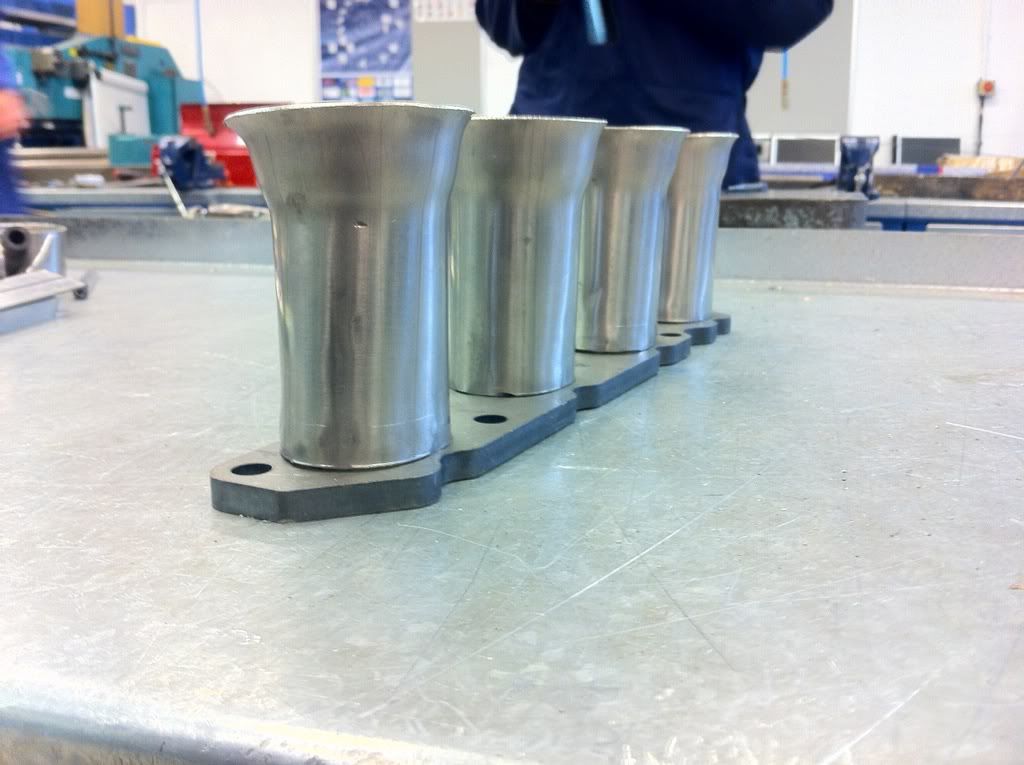
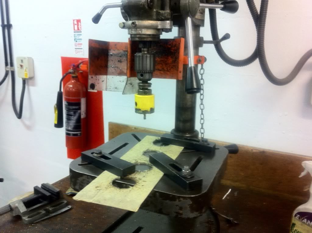
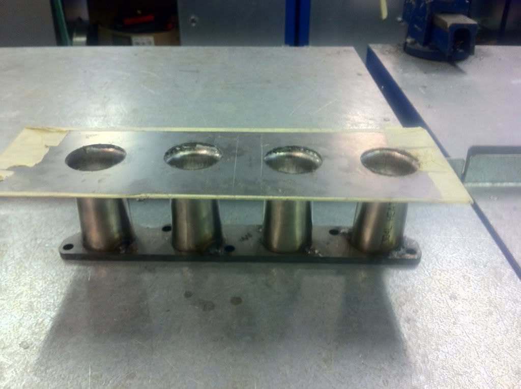
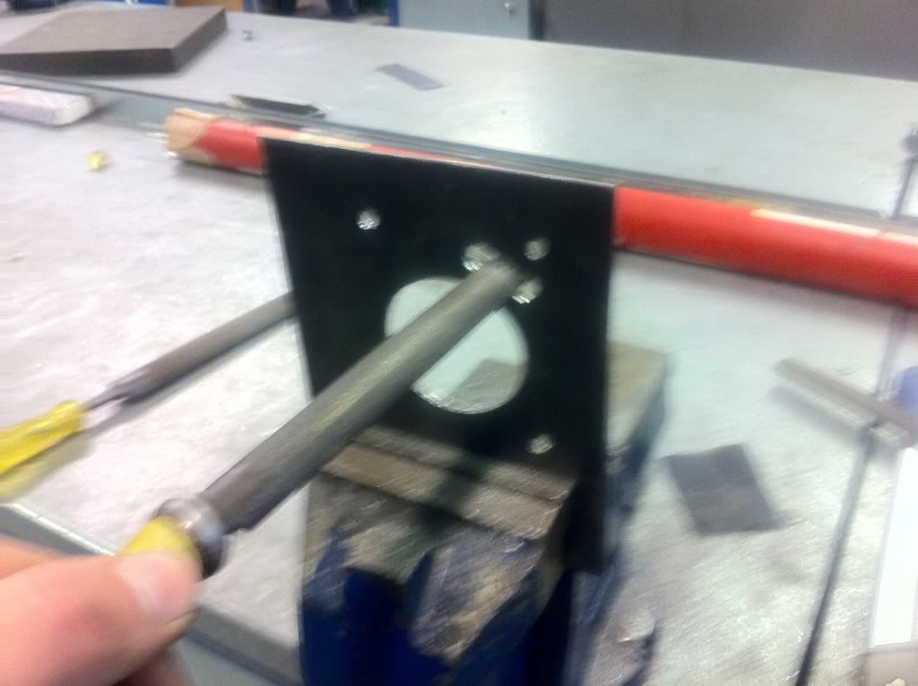
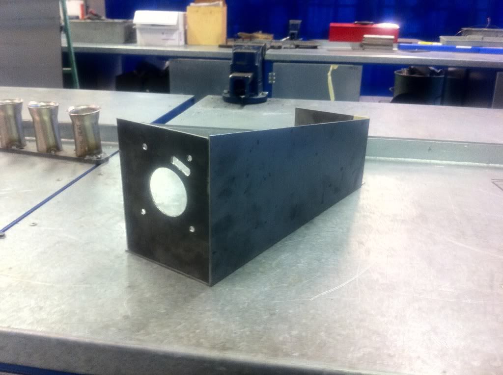
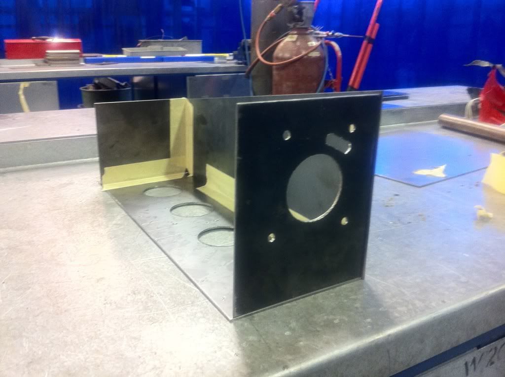
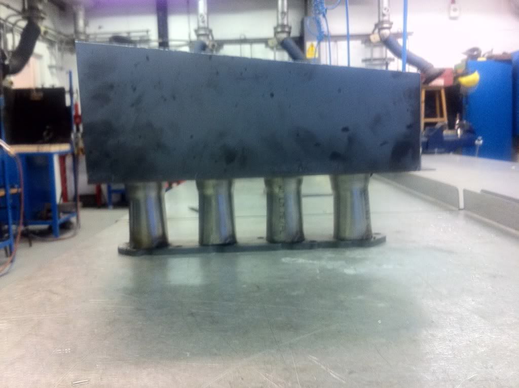
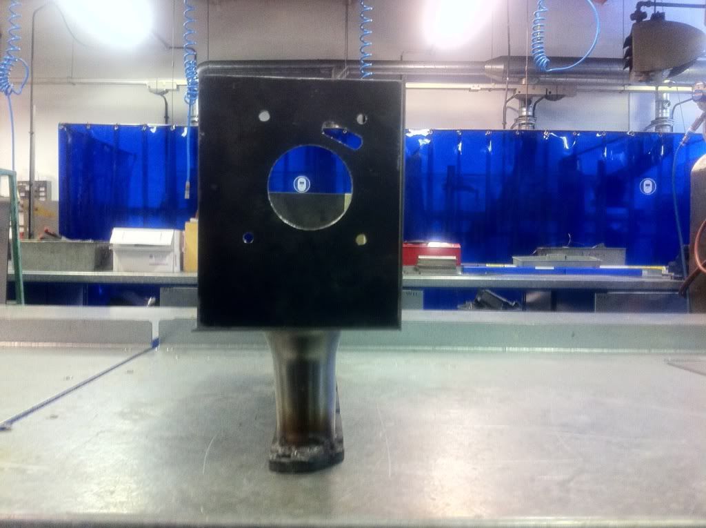
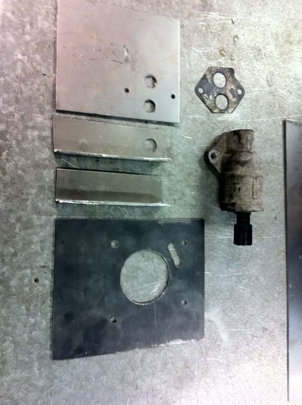
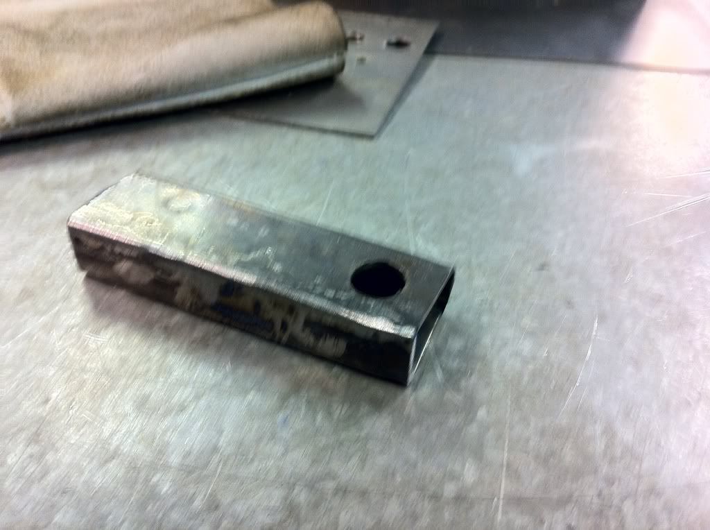
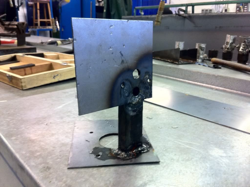
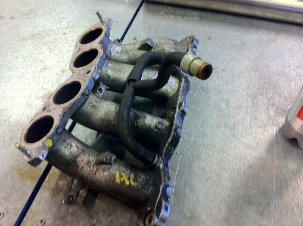
I am currently doing a degree in 'Autosport Engineering & Design' so for my major project I decided to build an intake manifold that benefits from the effects of pulse tuning for the Puma :)

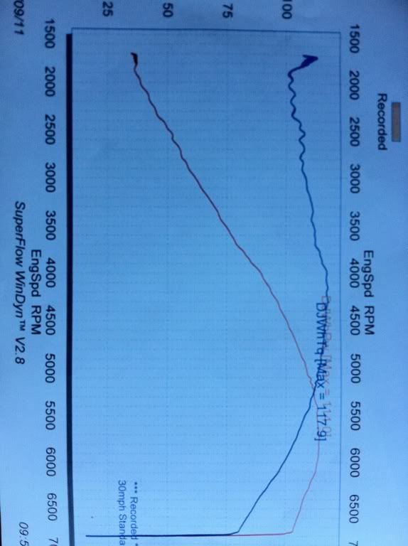
So, to see how the puma was performing, I put in on the Uni's rolling road... I will note, the Puma hadn't been serviced at the time, the tyres could have done with a top up of air and the air box has been chopped up (sounds nice but will be robbing it of a horsepower or two), nevertheless it produced a fairly healthy 114.0bhp and 117.9ft/lb, with a top speed run of 132mph.

e6222f4c.jpg


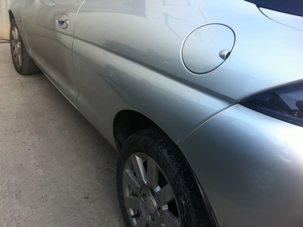
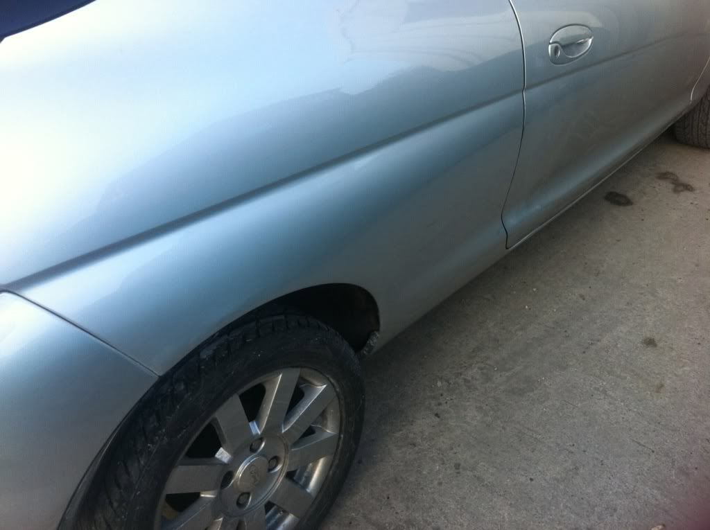
Next up was to tackle the rust (cheaply) - it was getting really bad, so without spending loads of money on a professional job, thought I'd have a go myself...

2f8f39ac.jpg

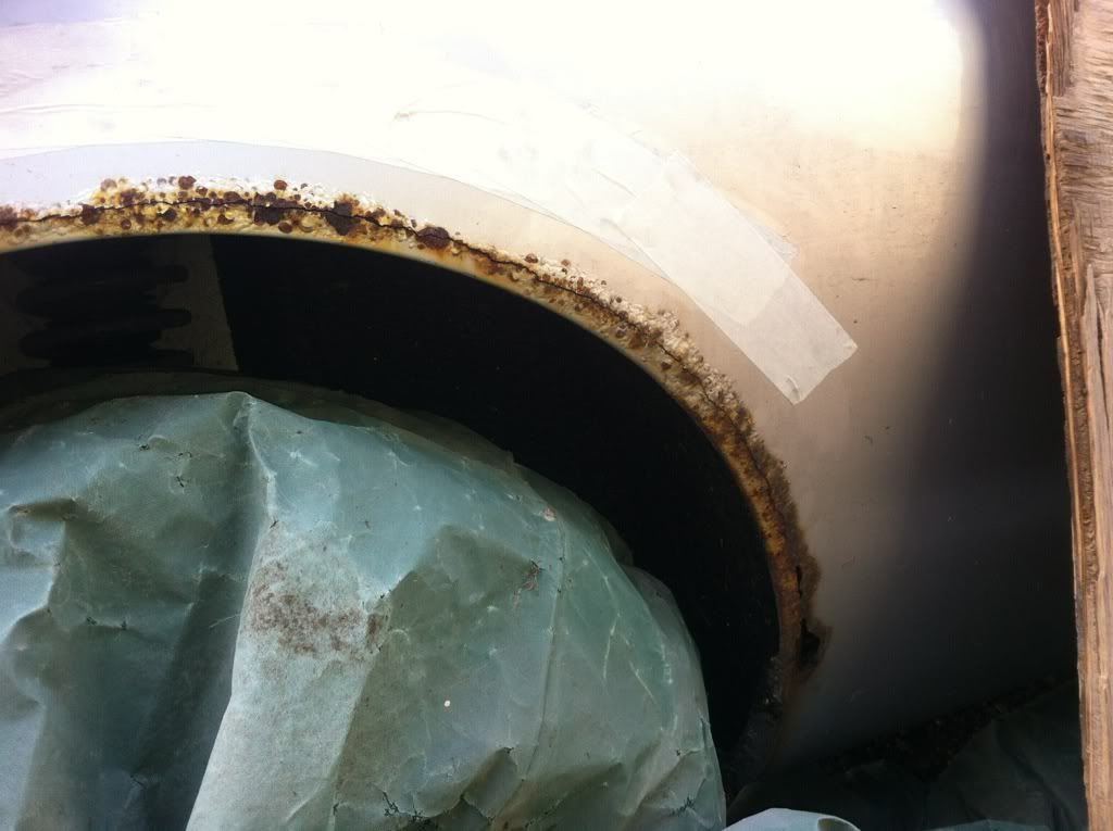
(this is the worst side)

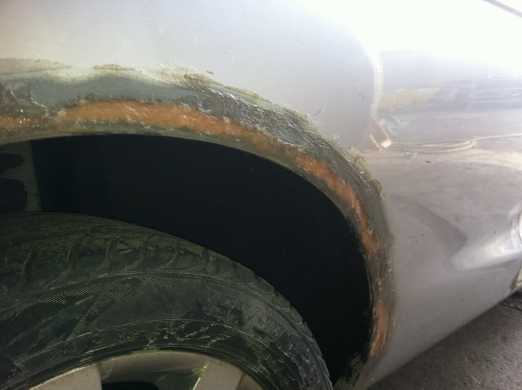
Fortunately my girlfriends step-dad works as a sandblaster, so i got him to blast the rust off both arches.

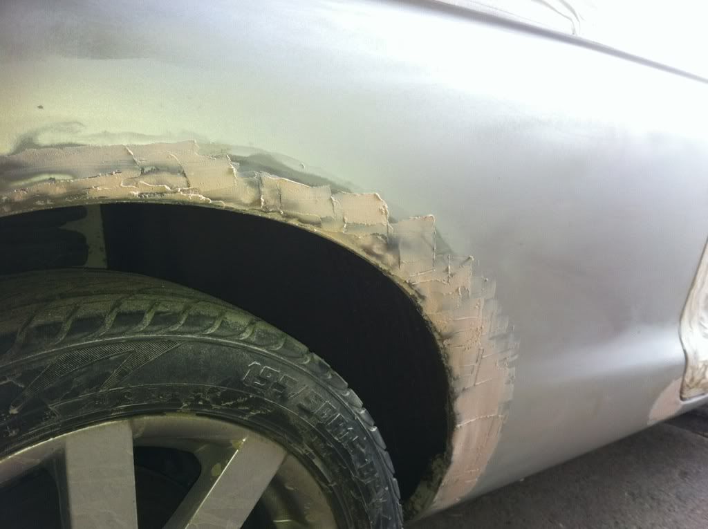
For about £3 I bought some fibreglass putty, filled the big gaps brilliantly...

aa9cb1ca.jpg


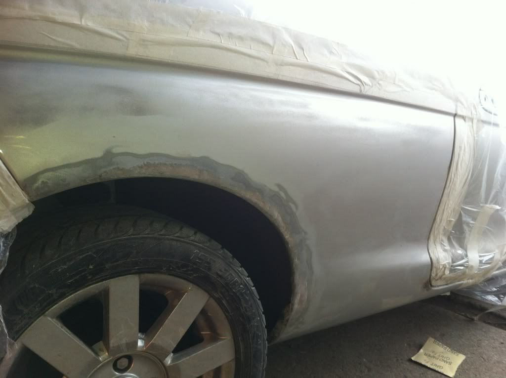
Sanded and then skimmed with normal filler...

4f0bbdf0.jpg


Then sanded...

77c633c8.jpg

af6131c6.jpg


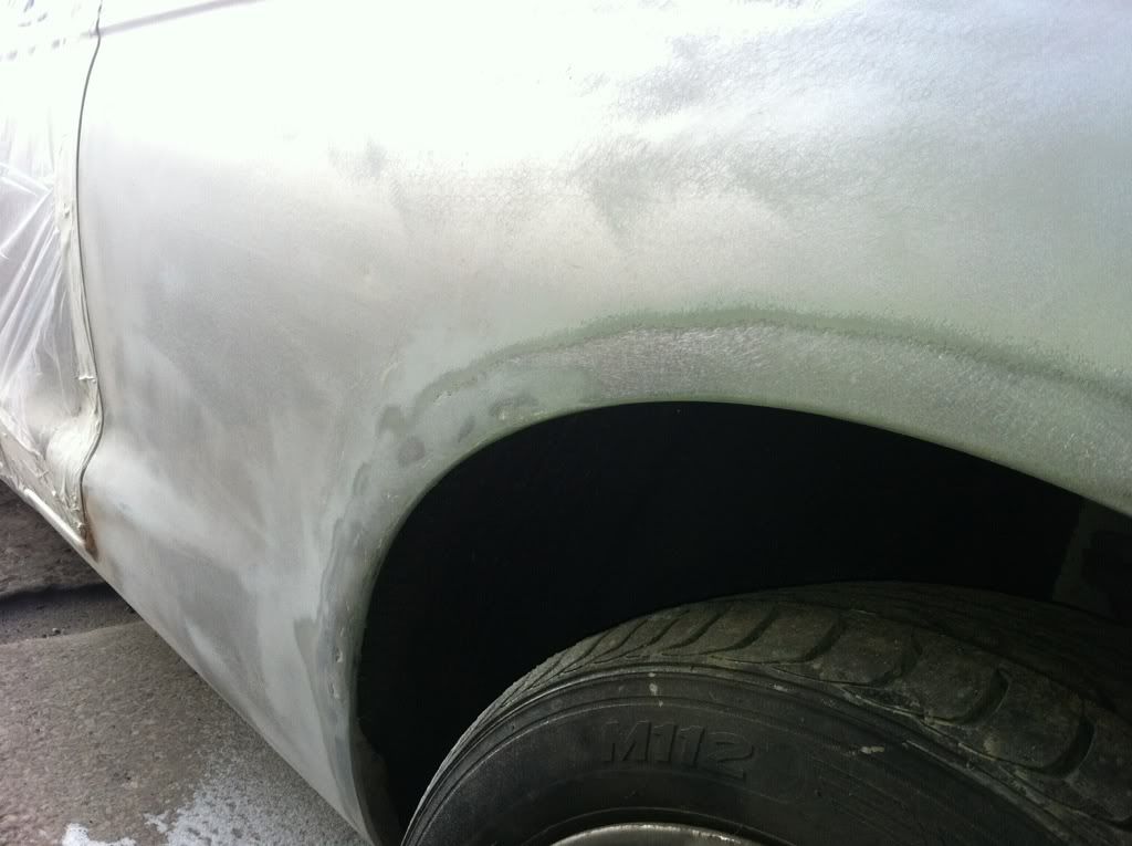
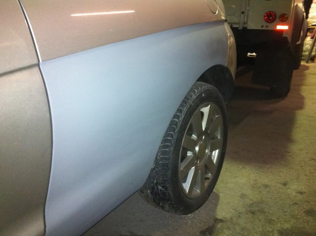
First coat of aerosol primer...

b3438dec.jpg

a0aaa053.jpg


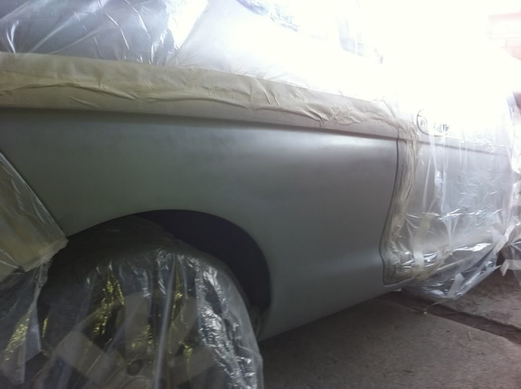
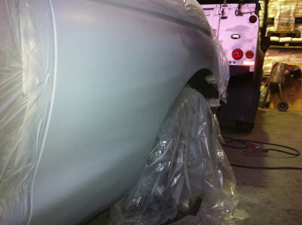
Second coat, and unmasked...

899cec95.jpg

e3cc6cdc.jpg

bad50cca.jpg


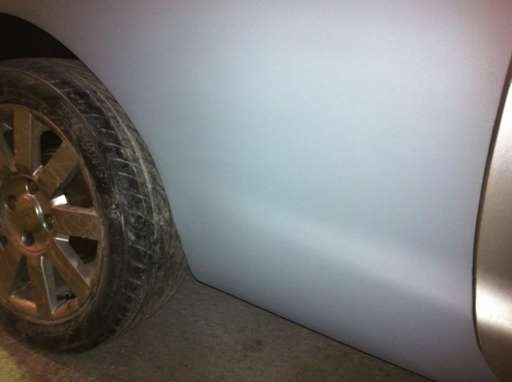
Then had the guy in the next unit paint it...

c6698e80.jpg

5d409188.jpg


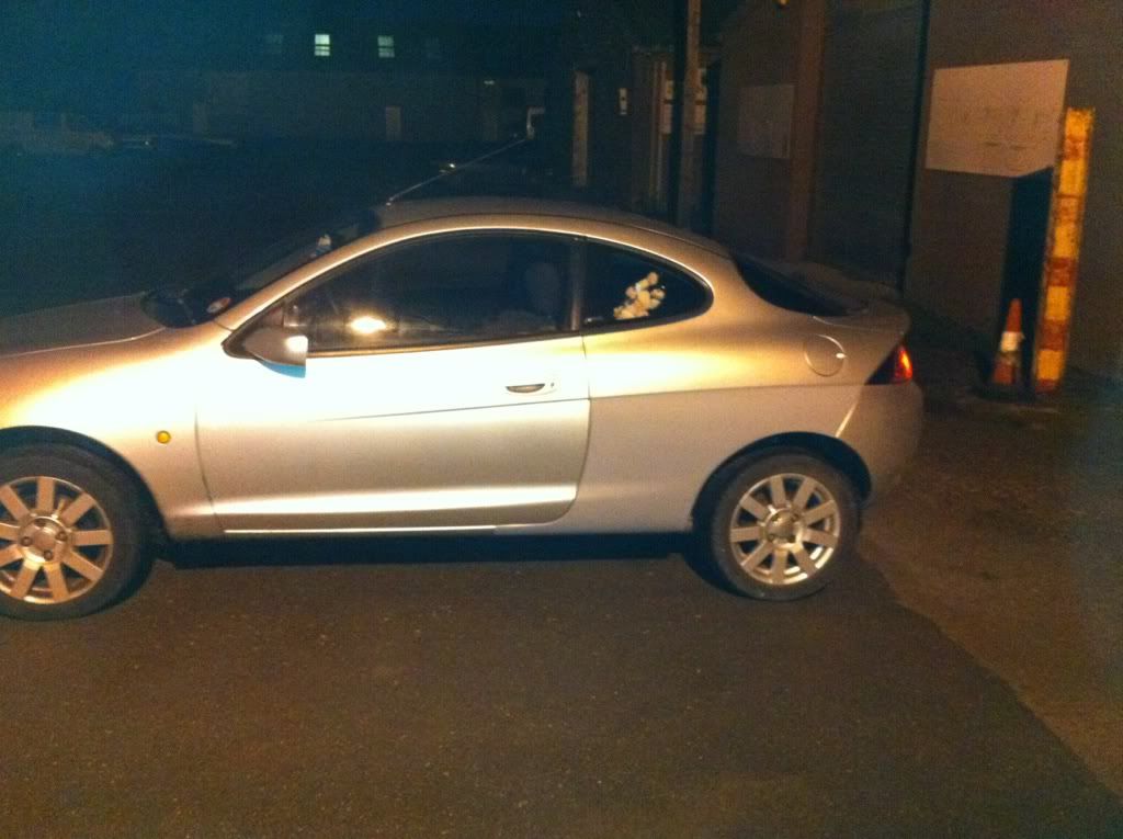
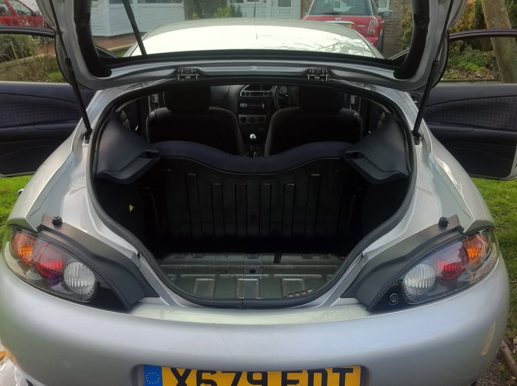
Cleaned all the dust out... (this is the only picture I can find thought)

9e90ece3.jpg


Next up is the intake manifold...

Lee
 
Goodstuff. If you're keeping it long term might be worth doing a lot more rust proofing underneath and possible inside via removing the rear seats etc. You may also find the rust returns quite quickly :(

Where are you studying?
 
Welcome to ProjP :eek:k:

As already said rust does return pretty quickly so make sure you treat the other side aswell. Waxyol does a pretty good job at protecting it aswell..

Keep us up to date with your progress :thumbs:
 
Welcome, I'll be following this thread with anticipation to find out how you get on with the intake manifold. I've had some thoughts and investigated about intake manifolds with regards to the pulse effect. Just hope you put on here what you find.
Nice work on your puma :eek:k:
 
This is what I managed to get done today and yesterday on the intake manifold...

I bought a flange from eBay as the plasma cutter wasn't working :-( and some 45mm pipe with an internal diameter of 41mm (ideally wanted 40mm I/D, but this is the best I could get...

As the flange was stainless steel, I had to use stainless pipe too, which is annoying as it's much heavier than aluminium, but never mind...

5feb1dae.jpg


The first 60mm needs to be 40mm, then increasing to 56.6mm I/D up to 90mm, so I flared it on a press, amazing how much stainless can stretch!

c05771db.jpg


59fff72b.jpg


Then I shaped the base of the pipe to match the port shapes...

5560a644.jpg


Next I drilled the 60mm holes into the base plate of the plenum...

f2ccd3cc.jpg


8281c79f.jpg


Machined the throttle body plate (having a go at sorting a way to fit the IAC valve tomorrow :| )

96c5fba3.jpg


Cut out the sides to the plenum and attached them together with masking tape, not sure if it will make a good seal though :lol:

809abf81.jpg


15708afe.jpg


7724ff35.jpg


f50d1c63.jpg


Will post some an update tomorrow too if I get time...

Lee
 
Ginger Tom said:
Welcome, I'll be following this thread with anticipation to find out how you get on with the intake manifold. I've had some thoughts and investigated about intake manifolds with regards to the pulse effect. Just hope you put on here what you find.
Nice work on your puma :eek:k:

To simply calculate the right diameters in the intake tracts; you need...
-Bore
-Peak power @ ?rpm (not to be confused with maximum rpm)
-Speed of sound within the temperature of the pipe

First the diameter must be calculated at certain distances from the back of the valve, I'm using 10mm increments, so the first calculation is at 10mm:

1. Piston area must be calculated, the Puma is 80mm bore, so simply Pi x Radius(squared)
which is 5027.2mm(^2)

2. The Port area is calculated by multiplying the piston area by the duct area, and a graph showing duct areas in regards to distance from the valve (will try and dig it out) which at 10mm is 0.3.
which equals 1508.16mm(^2)

3. The diameter is Square root the Port area, divided by Pi, multiplied by two to get the diameter, not the radius, which is 43.82. (The duct area number is the same for 0mm as it is 10mm, therefore this is also actually the optimum size the intake valve could be (theoretically, packaging issues aside))

This carries on to the optimum length, which is calculated by:

(angular displacement x speed of sound) divided by (0.012 x maximum rpm) angular displacement is 85, and as the temperature should be ambient, the speed of sound is 330m/s
therefore the optimum length is 417.4107mm to the inside of the intake plenum.

Hope this helps :grin:
 
Quick update...

Spend a lot of time trying to think of a way to mount the IAC valve, finally opted to have it inside the plenum (it will have a removable top so the valve is still accessible)

64bd9119.jpg


I had to make a bit of pipe to feed the air round to the valve using some steel sheeting...

f9762c91.jpg


Then mounted to the throttle plate and the IAC mounting plate...

d3716013.jpg


Seems to be ok, although i will have to raise the lid slightly as it sits slightly to high :roll:

Hopefully have it all welded together by tomorrow, then will paint it next week :grin:

Lee
 
not 100% sure which ones your on about,if your on about the 2 hose that are on the front of the inlet they are for the block breather.
 
They are two larger breather looking pipes that joint into one.. The flange I bought doesn't have the holes for it, so hopefully it will be ok blocked off and I'll just fit a catch can :)
 
Just a quick one, you can tell me to sod off if you want. If you have flared the trumpets to 90mm, why have you the fixed these to the bottom of the base plate and only drilled 60mm holes in the base plate, surely it would be more beneficial for the wave if you were to have the opening of the trumpets inside the plenum, thus causing less obstruction to the wave, no? Also, why have you decided on building a plenum that shrinks as it reaches no1 cylinder as surely the wave bounce from the back of the plenum will travel back to the back of the valves on no1 faster than the other cylinders? If any of that makes sense? :?
 
Ginger Tom said:
Just a quick one, you can tell me to sod off if you want. If you have flared the trumpets to 90mm, why have you the fixed these to the bottom of the base plate and only drilled 60mm holes in the base plate, surely it would be more beneficial for the wave if you were to have the opening of the trumpets inside the plenum, thus causing less obstruction to the wave, no? Also, why have you decided on building a plenum that shrinks as it reaches no1 cylinder as surely the wave bounce from the back of the plenum will travel back to the back of the valves on no1 faster than the other cylinders? If any of that makes sense? :?

No, your ok, Im open to any questions and/or criticisms (constructive ones only) firstly, they aren't the trumpets, they are just varying diameter intake tracts, there will be trumpets actually inside the plenum. The flared tracts are actually 60mm, just my poor grammar has made it sound confusing (I confused myself reading it just now lol) I meant to say they start at a 41mm I/D and increase to 56.6mm I/D @ 90mm, not to 90mm :)

Secondly the wave doesn't 'bounce' off the plenum walls, *deep breath* as the intake valve is open, the air is rushing towards the open valve, as the valve closes, this mass of moving air will hit the back of the valve and increase in pressure (to approx 1.1 bar) this will then bounce off the valve and head back toward the plenum, leaving a slightly less pressure at the back of the valve (approx 0.9 bar) the mass of higher pressure air will carry on up the tract until it reaches the plenum, where it will just dissipate, this leaves the entire intake tract at approx 0.9 bar, therefore due to some law which I can't remember off the top of my head, a mass of air will rush into the tract to equalise the pressure, however the air will be at a slightly higher pressure than ambient, approx 1.1 bar again. With the tracts I have designed, this mass of higher pressure air should reach the back of the valve while it is open, therefore theoretically increasing the volumetric efficiency of the engine. :grin:

The sloping design helps the air entering the plenum via the throttle body to be more evenly distributed, if it was rectangular the cylinders further away from the throttle mount would be more likely to have less air available to them *in general*
 
Ahhh gotcha with the inlet track lengths and diameters.

From what I have read and how I understand it the pressure wave acts in a similar way to sound waves and is wanted at the back of the valve as it opens to maximise VE and premote scavenging.

I'll take your word on the plenum as my ideas envolve a tubular intake manifold, though from what I've seen of n/a tuned engines most run with the single sized plenum, ie not sloping
 
I think the different designs alter the way the performance is produced.. so smaller and single sized plenums are good for throttle response and torque, but bigger sloped ones are for purely bhp gains* at high rpms or in forced induction applications.

*note that I don't mean a single sized one won't produce bhp gains, it will probably produce a better performing engine in real applications, but this build is primarily for my degree so I have gone for purely highest bhp gains, I will probably lose a lot of torque and low down power as a result.

Hope this makes sense lol
 
Lol yeh it does.

Depending on your findings and how deep my pockets are once I've got my car running will determine which way I take my intake manifold, whether to go with a plenum or tubular. Like you say your aiming for one target where as I'll be looking for several when I come to design my one
 
I think so far I have spent about £50 in the flange and stainless piping, with about £20 worth of mild steel sheeting which I have aquired for free from Uni. So just as a 'have-a-go' mod it's not breaking the bank :)

I deliberately made it so focused on peak performance as it allow me to redesign it next academic year for my dissitation as I will be able to use CFD to flow it properly and actually make a more general gain in performance (improving the area under power and torque curves opposed to peak power) Hopefully this will also include a working plasma cutter or similar to make a sort of intake plenum jigsaw puzzle instead of hand cut parts, in which case I will be more than happy to share the designs with anyone wanting to build their own (as long as it works lol)
 

Latest posts

Back
Top