The rebuild of no 219

ProjectPuma

Help Support ProjectPuma:

This site may earn a commission from merchant affiliate links, including eBay, Amazon, and others.

richard_rip

Member
Joined
Dec 20, 2016
Messages
78
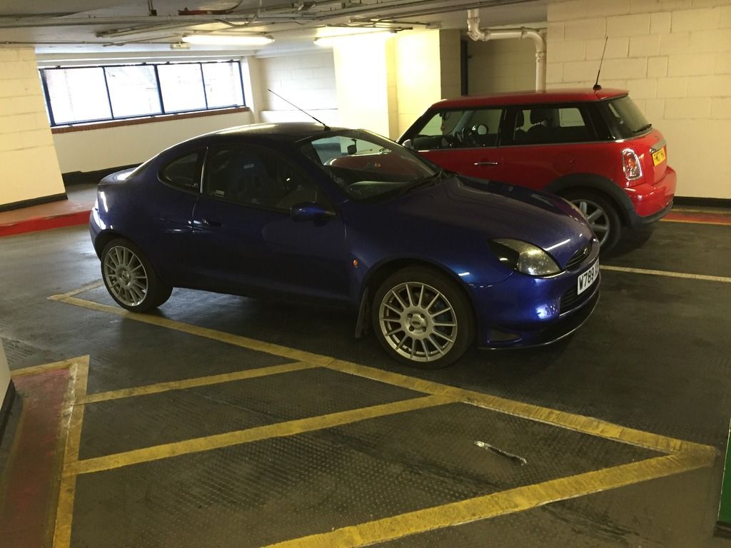
Hi. I thought some of you might be interested to see the work I'm carrying out of number 219.
We bought her in September 2015 off a chap in London and it had 140k on the clock, he'd had the arches redone and the wheels refurbed but mechanically it had quite a few bits wrong.
This is not a complete list of problems
Clutch was slipping
Accelerator pedal wasn't right
Idle was poor
Leaking a bit of water from somewhere
Kangaroo'd when you accelerated
Indicator stalk didn't work
Passenger window didn't work

The idea was to have this as a weekend/summer car and give me a little project. I've always worked on cars and earlier that year I'd rebuilt the head on a Renaultsport Clio 197 which isn't the easiest of tasks but I really enjoyed it. I'm a precision engineer by trade so I'm a bit of a perfectionist and the idea of a car needing a lot of TLC really appealed to me.

A couple of weeks after we collected her
C95FE9B8-63C5-4552-B6D6-793B64E0A575_zpsg8hc23sw.jpg


I started easy, changed the window regulator, picked up a new unit for the indicator stalks, and new fuel sender unit. The sender unit fixed the kangarooing but it turns out the wires on the fuel gauge were the wrong way round so it reads backwards on the dash, which I kinda like so haven't changed it yet haha.

After a few months of owner her the small water leak had become a haemorrhage, turns out the head gasket was shot as well. I decided I'd do a full and proper job on it by rebuilding the entire engine so I put it under cover until better weather, not to mention the fact we decided to move house.

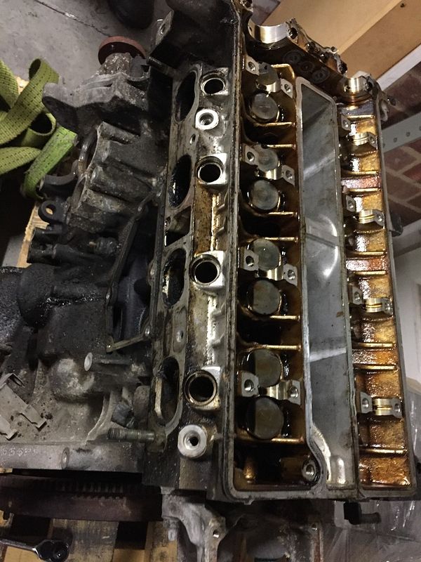
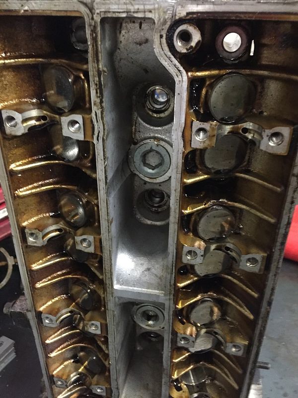
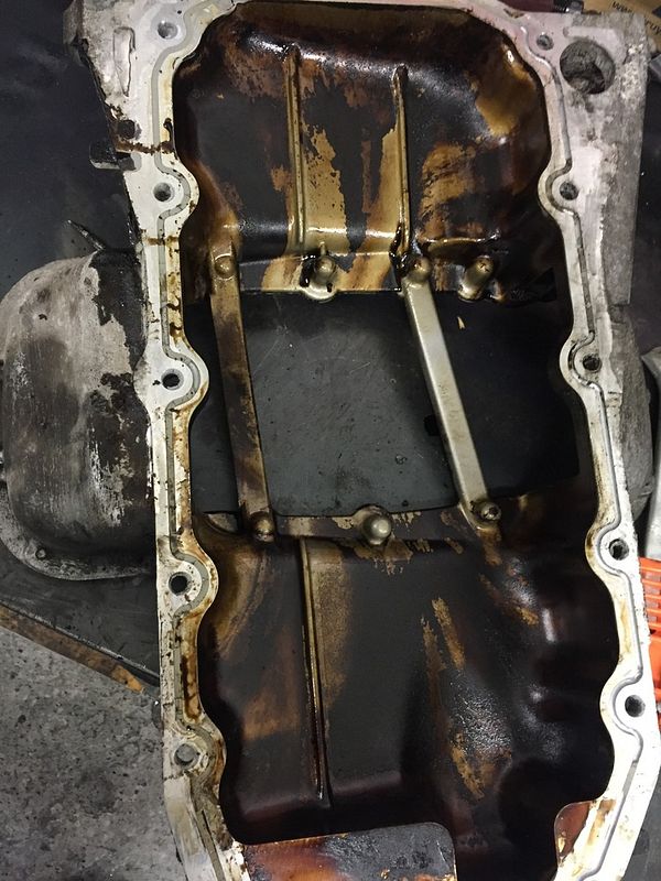
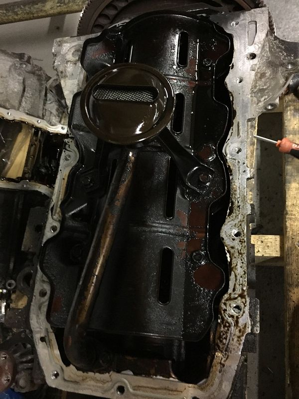
With the original engine having done 140k miles I was worried the bores would need recoating/honing so I decided to "practice" on a lower mileage engine off eBay. For £150 I went and collected a standard 1.7 unit with 78k miles on the clock and the plan was to the FRP bits in it from the current one. It was a little grubby

8F7E70D4-0311-4CCF-8065-C233B27FC9C8_zpsrn948ku0.jpg


C5741181-6BED-43A2-BE6D-5A7231275727_zpsu2ubyp7k.jpg


0FD76B0D-43DA-4BEB-84BA-C0D3CAE7A30F_zpsppjy2lvi.jpg


D0F495A6-D842-4290-BF14-4ED62C4C3711_zpspvmhy6cd.jpg


5BAFFAEE-6AE7-43F5-BBA7-E2E9C80CDBFE_zps9zo55fgi.jpg


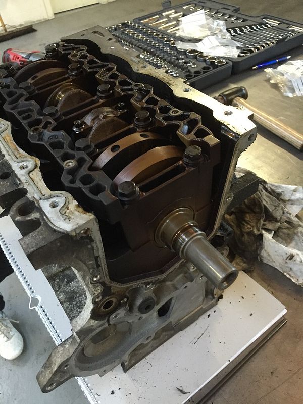
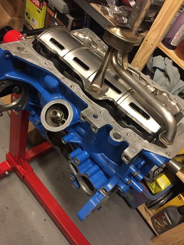
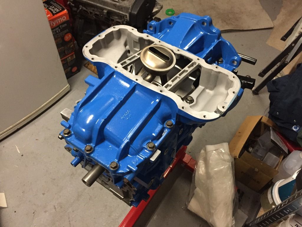
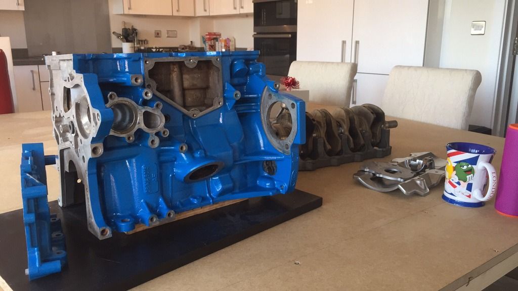
The first job was to get everything clean again and I decided to paint the engine a similar colour to the brake callipers, I know it's not to everyones taste but I wanted to give it a try and this was the engine to try it one.

95433914-F81E-4C2A-A5B6-70B018332733_zpskdf58vwt.jpg


FF5B4A72-9AE4-4C96-92BD-0269AA86753E_zpshyxlo3hn.jpg


5C58DC05-CB06-4F23-AFD2-C30736A5EA10_zpsxl4pvx12.jpg


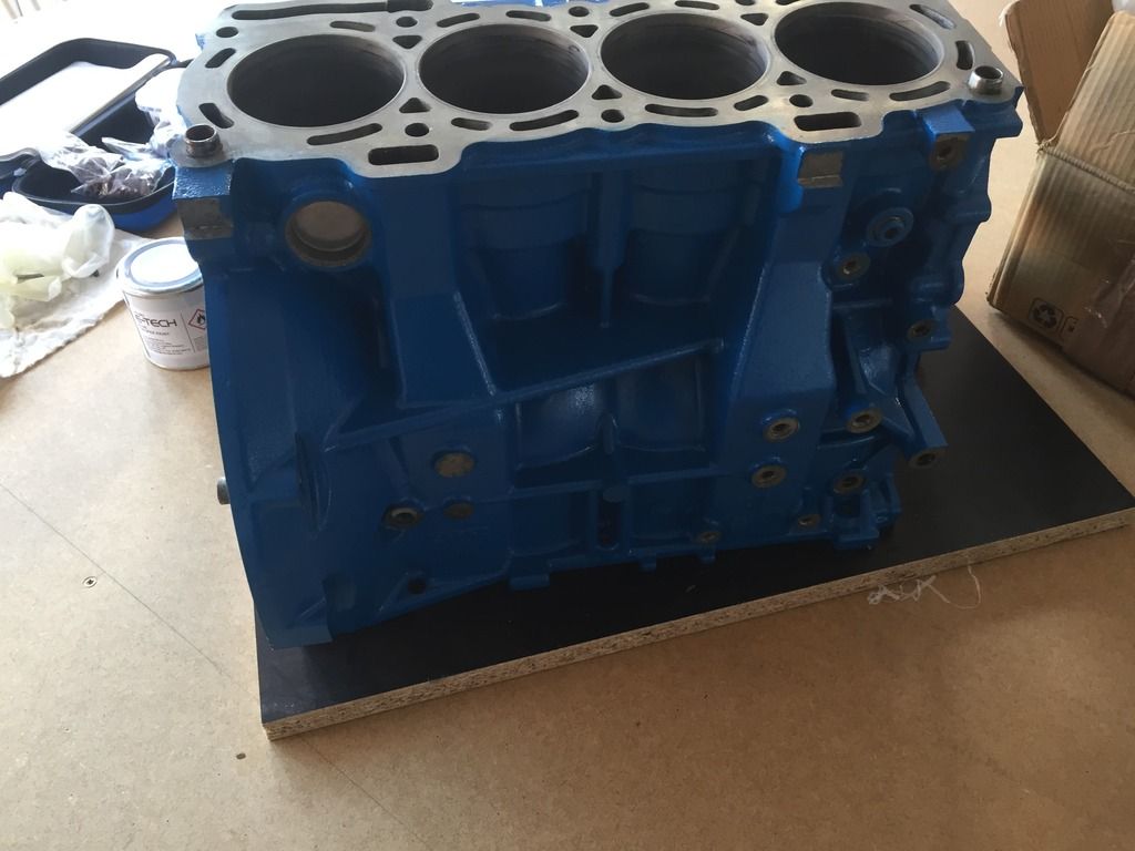
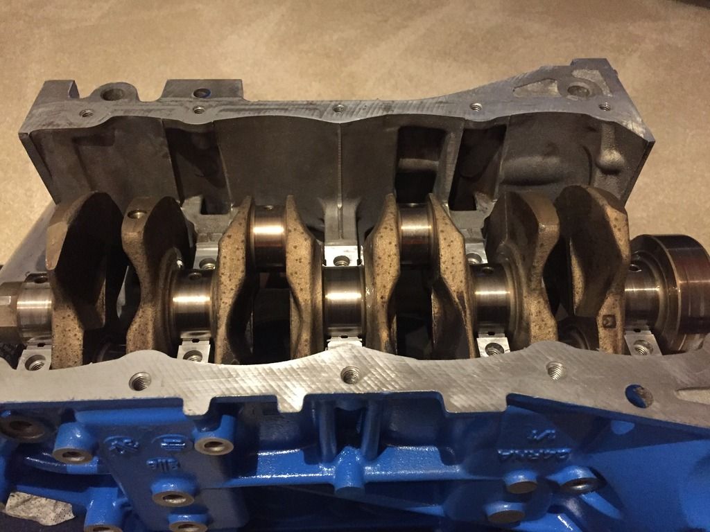
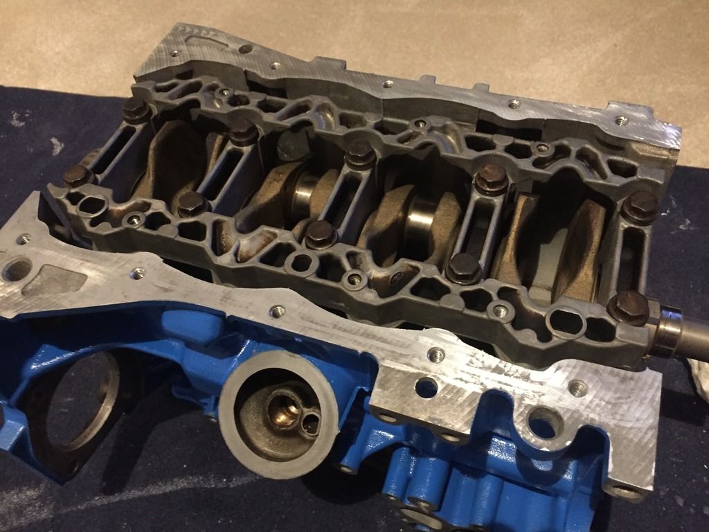
I took the block and head into work to test the bores for diameter and taper, both were within tolerance to Ford spec. I also checked the contact faces that the head gasket sits between for flatness, both the block and head were flat within 0.03mm

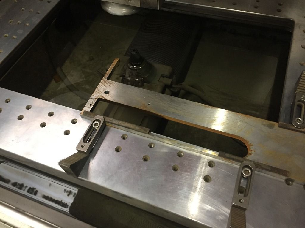
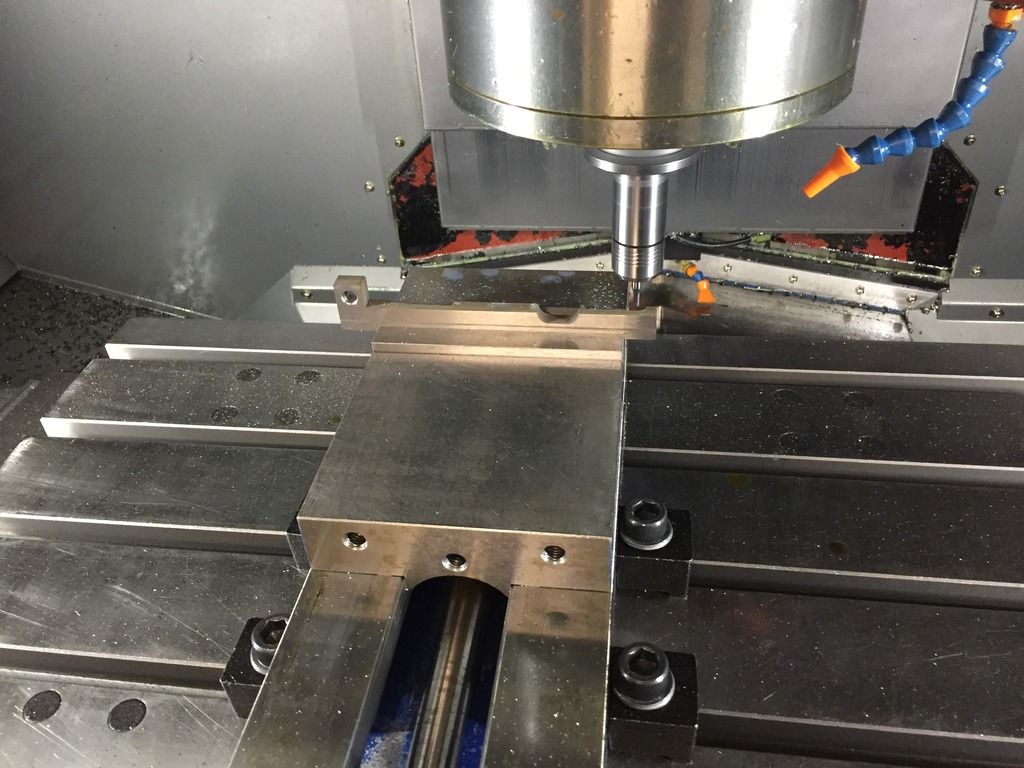
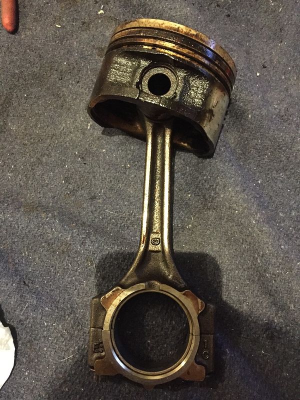
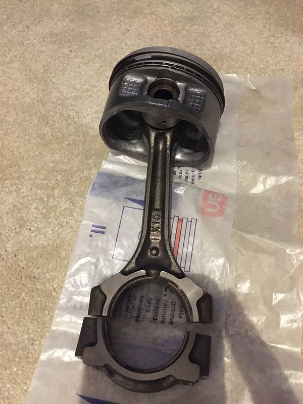
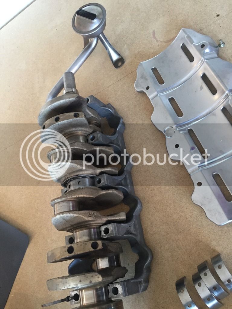
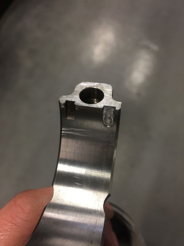
I measured the clearance on the big ends and mains and it was right on the limit of spec so I decided to change them all. The mains were easy to get but the big ends were a different matter. After much searching, a few sets delivered that didn't fit, and a bit of help from some on PumaPeople, I found out that big ends from a Mitsubishi engine were the correct size. The only problem was that the location pip was on the wrong side so another trip to work was required to.

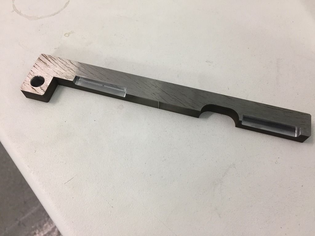
I set the journals and rods up on a milling machine, they weren't as hard as I was expecting
FC6D8E18-902A-4732-804A-022A33A69CC0_zpsrqhbfzqh.jpg


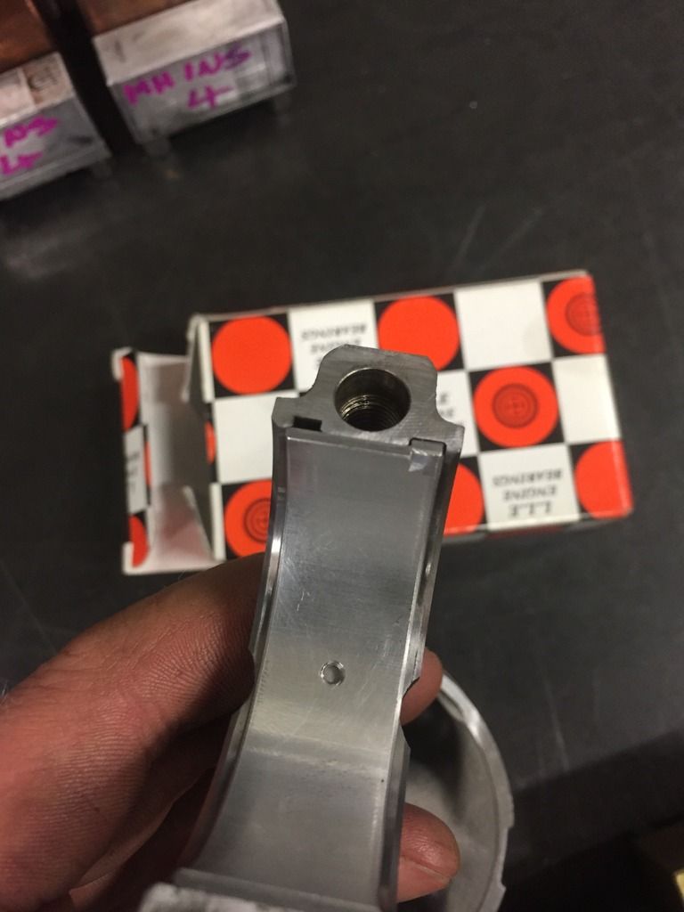
The new shells after I'd got the size and position just right :)
0EF45AD3-AE27-47E8-B46A-23555382AF7C_zpsst6qvmnj.jpg
 
Looking good! I think it may have been me that shared Sinisa's info on the big ends - he did all the hard work I can't take any of the credit!

The gauge reading the wrong way means it's the wrong sender in afraid, it'll work fine, just read incorrectly.
 
XAF said:
[post]360510[/post] Looking good! I think it may have been me that shared Sinisa's info on the big ends - he did all the hard work I can't take any of the credit!

The gauge reading the wrong way means it's the wrong sender in afraid, it'll work fine, just read incorrectly.
A big thanks for sharing :)
They worked a treat and the clearances are spot on now
 
The next job was to get the crank back in and checked
F61392BA-DC73-445D-BA70-BF5F56200652_zpsn88jv8ue.jpg


I spoke to Shawspeed about the mains and torque settings etc for the crank ladder, after a bit of living room floor rebuilding (on a rug to keep the misses calm obviously) this is what I ended up with. They recommended 50Nm for the main bolts btw, I don't know why Ford say the block and crank are a non serviceable item as it seems pretty easy.
7920E0E3-C126-4628-A2D8-70F7C398A529_zpse7xlf0pd.jpg


[youtube]https://www.youtube.com/watch?v=ndghjyd5644[/youtube]

I also made sure that the end float was correct, the Ford value on it is between 0.22mm and 0.43mm so at 0.29mm I'm happy
[youtube]https://www.youtube.com/watch?v=TmpxqdzplIs[/youtube]
 
Hi Rich, nice going on the FRP & the work :eek:k:
Always love it when there's a nice engineering thread detailing dimensions, processes etc. etc. - not that I'm skilled enough to do it myself but it all adds to the general knowledge base and you never know, one day. Especially if there's a nice detailed, step-by-step, 'How To Guide' of course :wink:
Not sure how much of a help it will be, as it was rather light on specifics IIRC, but there was an engine rebuild thread a few months ago, might be of some use? Here:
http://www.projectpuma.com/viewtopic.php?f=51&t=16125&p=353456&hilit=Engine+rebuild#p353456
Also, as James (XAF) mentioned, Sinisa ( Wild E Coyote) does really good research work on the engineering side, might be worth checking his thread out, there are a few others too... just definitely not me! :lol:
Look forward to seeing this progress, have at it! :eek:k:
Greg.
 
g-whizz said:
[post]360520[/post] Hi Rich, nice going on the FRP & the work :eek:k:
Always love it when there's a nice engineering thread detailing dimensions, processes etc. etc. - not that I'm skilled enough to do it myself but it all adds to the general knowledge base and you never know, one day. Especially if there's a nice detailed, step-by-step, 'How To Guide' of course :wink:
Not sure how much of a help it will be, as it was rather light on specifics IIRC, but there was an engine rebuild thread a few months ago, might be of some use? Here:
http://www.projectpuma.com/viewtopic.php?f=51&t=16125&p=353456&hilit=Engine+rebuild#p353456
Also, as James (XAF) mentioned, Sinisa ( Wild E Coyote) does really good research work on the engineering side, might be worth checking his thread out, there are a few others too... just definitely not me! :lol:
Look forward to seeing this progress, have at it! :eek:k:
Greg.

Thanks.
When I come to rebuild the cars original engine I might go to town on it, there'll be a lot of pics for that I now what I'm doing haha
 
The next couple of jobs were done at work
The flywheel looked a bit messy so I though I'd sort the face of it while I was doing all this work.
EC112E12-B212-47C7-9DAE-78477D2B5F5B_zpsmgviwuk9.jpg

I removed the pins, lay it on the front face and ground the back of the wheel to give me a nice clean face for the magnetic table.

0.12mm later and it looked like this
A7B5BA96-B8DD-4354-8C48-6DC4E511F0FC_zpsai7veu6u.jpg


I then turned 3 new pins and hardened them.
Given that I'd need to time the engine at some point, and timing tools were hard to get hold of for the FRP I decided to make one after I'd found someone drawings of the tool on the net.
First to wire erode the blank
5C725B3B-5FEA-45B1-9C8A-34BF258B4BF4_zpstsrg0jsk.jpg

Then onto the Milling machine to put the slots in
54874E1B-39F7-40C8-962D-314876E0B988_zpso7g8ustz.jpg

And here's the finished part. I tested it on the original engine before removing the cam etc and it was perfect :)
B035C108-F719-4BFA-BD6D-548B1F321FB2_zpsato2akdh.jpg
 
Wow! Love it. Attention to detail, pics and facts make these threads brilliant. As Greg says, not that I have the skills to replicate!
 
Very nice! Would you, please, give me the exact coordinates of milling the conrod and big ends to take on the new bearings and to avoid the dremelling the location lugs to make them fit?
Or did you do it by trial and error?

Cheers, mate!

PS. For the rest of interested parties, I have discovered the Suzuki 1.3 bearing (from Swift and Liana) are exact match. I am still waiting for the reply from a mate working at Suzuki to give me the service dimensions on these (they are supplied in 3 or 5 classes) and that would make it possible to mate them to Ford specification exactly as it is colour coded in TIS (to 1/1000 of mm). That would make it effectively a BRAND NEW bottom end
 
richard_rip said:
[post]360514[/post]
I spoke to Shawspeed about the mains and torque settings etc for the crank ladder, after a bit of living room floor rebuilding (on a rug to keep the misses calm obviously) this is what I ended up with. They recommended 50Nm for the main bolts btw, I don't know why Ford say the block and crank are a non serviceable item as it seems pretty easy.

I think the word to be used there is greed/greedy as I thought exactly the same thing. The engine is built to the very same standards that are applied across car industry
 
stuvy said:
[post]360528[/post] Top work very envious of your facilities

Being an engineer can be an advantage sometimes, and I have a great boss who doesn't mind me using everything at weekends

Wild E. Coyote said:
[post]360535[/post] Very nice! Would you, please, give me the exact coordinates of milling the conrod and big ends to take on the new bearings and to avoid the dremelling the location lugs to make them fit?
Or did you do it by trial and error?

Cheers, mate!
It was a little bit of trial and error, I used a 4mm carbide cutter in a long series 10mm diameter holder. Then held the journals in a vice at an angle to the point were it didn't hit the holder, if that makes sense. I milled the slot 1.5mm in from the edge and to the same depth as the slot on the other side. I'm going to be doing the set from the other engine so I'll do a video :)
 
Onto the pistons, I had to get them clean again as I'd picked up a new set of rings to fit.
Before
1B4ABC2D-329F-46D1-8E64-88B97D311069_zps2bzifjcx.jpg

With the new rings in and cleaned. All the rings were gapped to ford spec for each cylinder and were ready to go back in the block
2A9EB183-3437-4900-A37A-DBACC50FB261_zpsqn9rzjna.jpg


Picked up a cheap engine stand off eBay for the bargain price of £37 and the block rebuild began. I stripped, cleaned and rebuilt the oil pump for good measure as well.
4629C8C8-B13D-41B0-B9A4-851C9F79C37E_zpsgbnpsmco.jpg


Upper part of oil pan sealed and bolted back on
6B2101B1-8501-4554-B832-FAB024A37F41_zpsdbcqu5ej.jpg
 
What rings did you use? If you used the Honda A18A for accord set from NPR, you do realise the material incompatibility? The puma engine uses nikasil, and the rings from Honda which fit dimensionally are meant to be installed in cast iron block and are chromed (1st and 3rd - oil scrapper) and phospated (2nd). That will most likely end in destruction of nikasil.
Since the engine block uses nikasil, the piston rings should be nitrited (1st, 3rd) and phospated (2nd).
The only way out, as I see it, is to combine the two sets. Use the 1st ring only from Nissan QG18 Gasoline (80 mm bore as well) which is nitrited as it shuld be and thick 1.2 mm (again close enough).
The 2nd ring should be from aforementioned Honda A18A set as it is phospated.
The 3rd ring from the Nissan set is again nitrited as it should be but at 2.5 mm is probably not thick enough. I thought about it and came to conclusion that most probably the oil scraper can be left as it is as the 2nd piston ring will wipe down the excess oil anyway. Also, I don't think Ford made released any service dimensions for it anyway.
Again, for interested parties the cat number of NPR sets:
The Honda one (donor for the 2nd compression ring IMHO): 79 7643 0000 (std, there are also 0.25 and 0.50 oversized sets)
The Nissan one (donro for the 1st compression ring IMHO): 79 9084 0000 (std, there are also 0.25 and 0.50 oversized sets)

I hope thgis helps and would like to know what are you using?
 
As Sinisa said, the 1.7 is very sensitive to the correct rings due to the Nikasil - I got a set from Ford and the price was ridiculous but as it was the last set in existence I had no choice. Well I did have a choice really, as I never used them!

There is a seller on ebay selling ring sets as being for the 1.7, and whilst I've no doubt it will run with them, how long is anyone's guess as the coating slower gets destroyed.

I have no basis for this next comment other than experience with my 150k Puma that Chris just rebuilt the engine on, but that's on its original rings still and no drop in compression or signs of wear at all. Runs like a dream.

And Sinisa, another awesome find with the combination of rings. How'd you work out which ones would work and which ones wouldn't! Amazing attention to detail.
 
Sinisia are there colour differences to identify which ring is coated with which?

Richard, I build car for a living and we have all the obvious tools. It a baby myford7 which my boss is a demon on!
 
I've just had a look through all the bits I've bought, the rings I use are indeed NPR :?
I'll see how they go with this engine given it's not the original engine. I get a lot of nitriding done through work, I wonder if I could get the chrome removed and then nitrided. Or I could look at getting the cylinders relined in steel?
 
stuvy said:
[post]360553[/post] Sinisia are there colour differences to identify which ring is coated with which?

The chromed rings will be matte in appearance. Nitrited rings will be very shiney. That is just as a general rule, of course all the new stuff is shiney by being new!
 
Back
Top