Carbon Chassis Project.

ProjectPuma

Help Support ProjectPuma:

This site may earn a commission from merchant affiliate links, including eBay, Amazon, and others.

warrenpenalver

Active member
Joined
Feb 18, 2008
Messages
1,687
Location
Stoke on Trent/ dole que!
I have decided that i want to see how crazy i can go and design a carbon chassis.

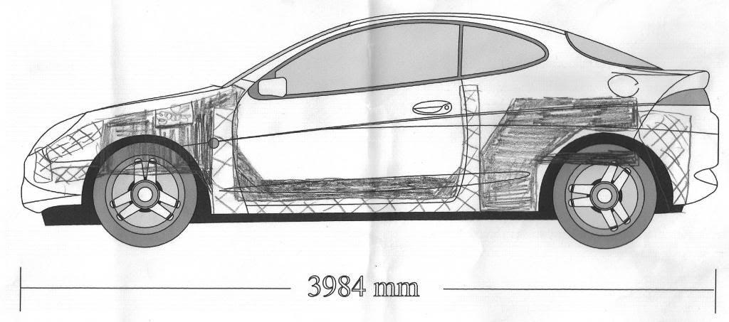
It will be based dimensionally around the wheelbase and rough dimensions of the puma but the body panels themselves will in essence be cosmetic/weatherproofing only.

This is not going to be a quick project so if youre hoping to see a carbon chassis built in the next few months then look elsewhere :cry:

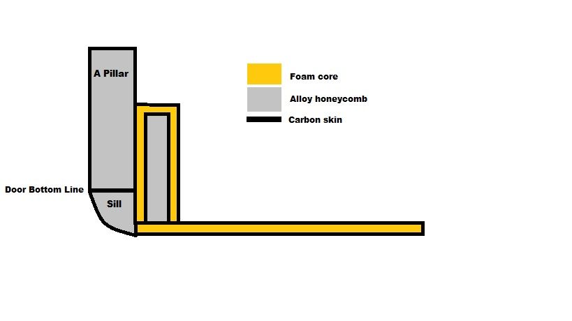
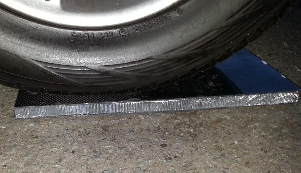
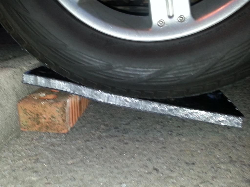
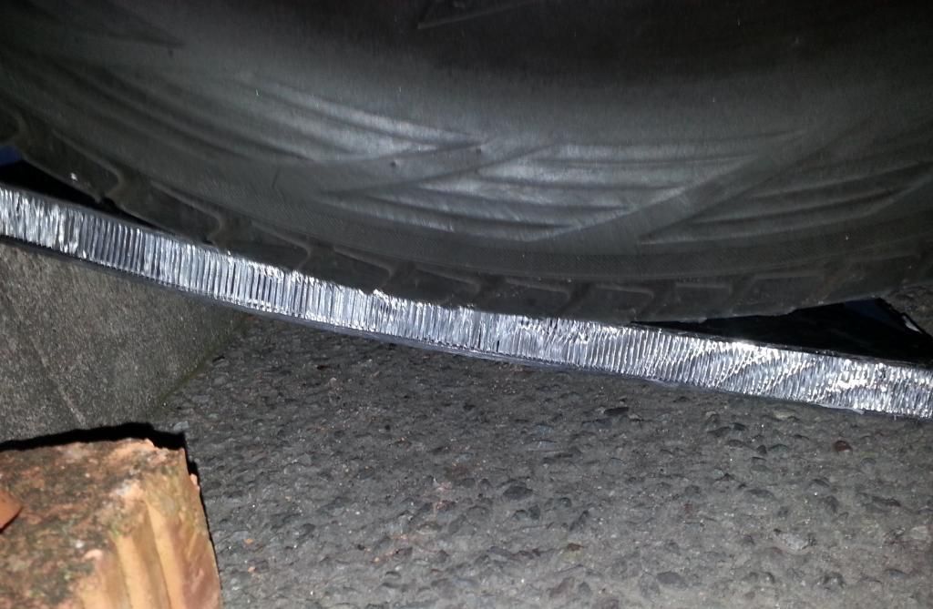
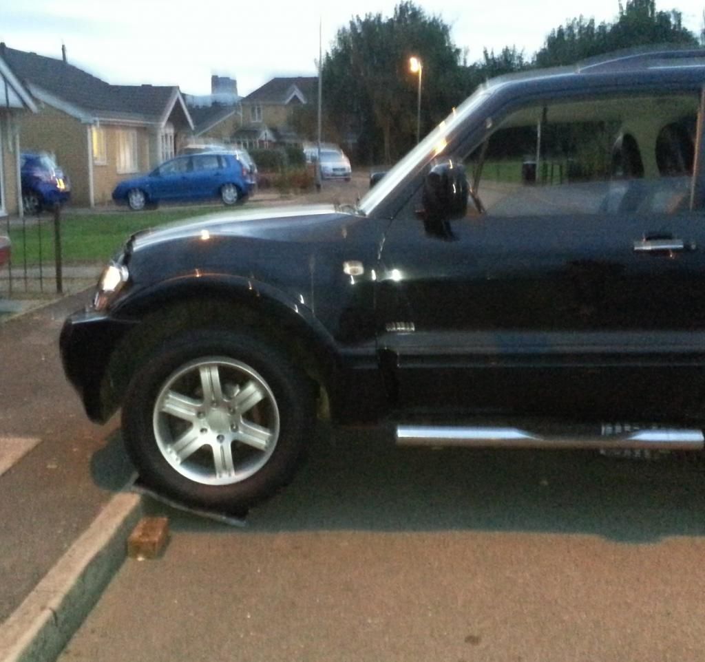
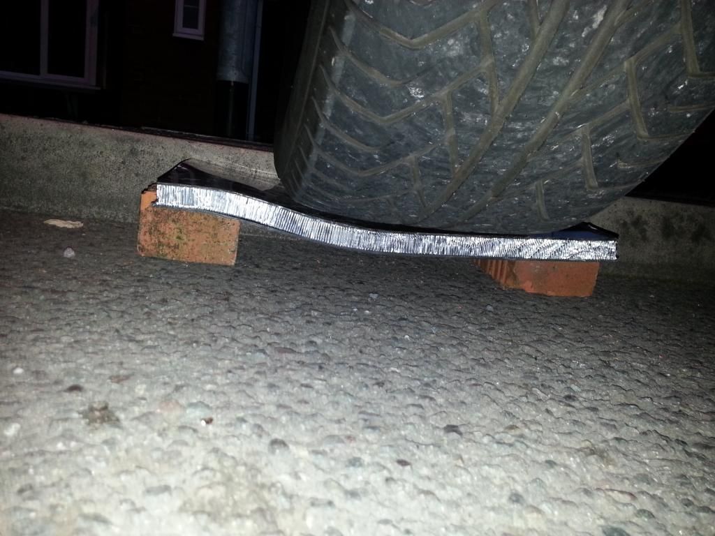
Initially its a design exercise, mostly in solidworks CAD along with some destructive testing of representative test panels etc to refine the design and structural strength as required.

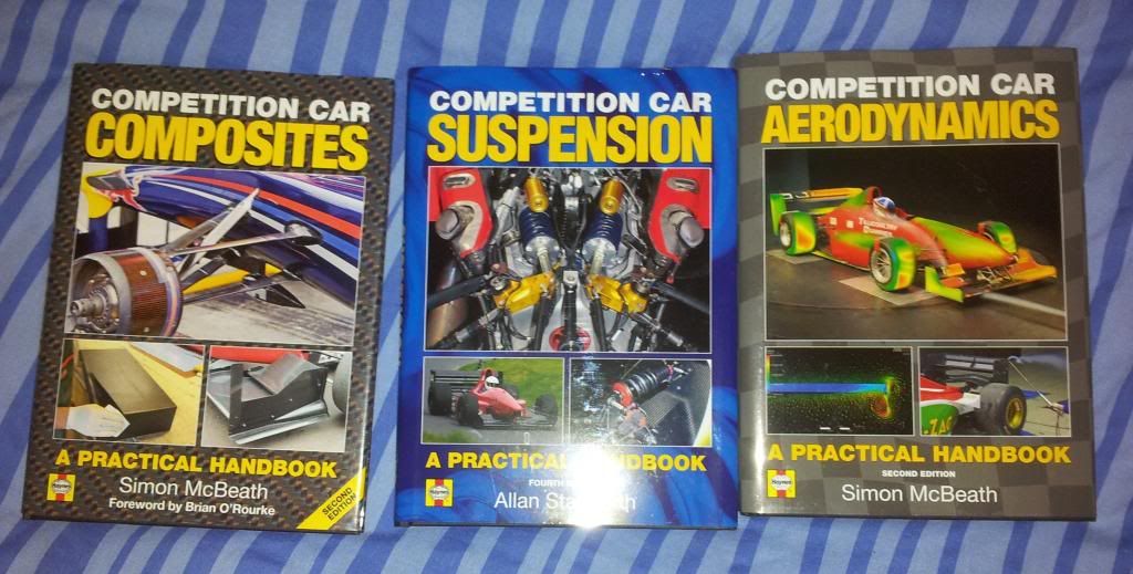
Hopefully if it works out feasable then i will build the chassis and as a full car. I already own over 100 square meters of carbon, most of the core material i need. The rest i can source through work at cost price so in terms of affordability, a simple monococque chassis isnt as expensive as you might think in material costs.

Firstly i need to re-learn CAD. Its all changed since i did it back in 1999/2000 and moved from being programmed by hand to being based on mouse commands and a simple menu interface. Should be able to learn it fairly quickly and much quicker than it took me to learn C and program in linux k-shell.........

A few fixed constraints,

Must fit within puma profile
same wheelbase as current puma.
Will be engineered for cossie drivetrain
ability to add steel roll cage if full roof and roll over protection not already built into design.

Im still in split minds about using cossie based suspension set up or going the full hog and designing a double wishbone set up front and rear. Have some suspension design reading to do over the next few months and a fair few calculations to work out what is the best way forward.

Few initial rough sketches based on cossie subframes and beam:

sketch2.jpg

sketch1.jpg

sketch3.jpg


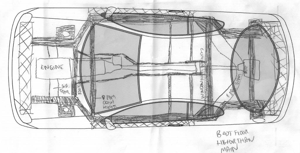
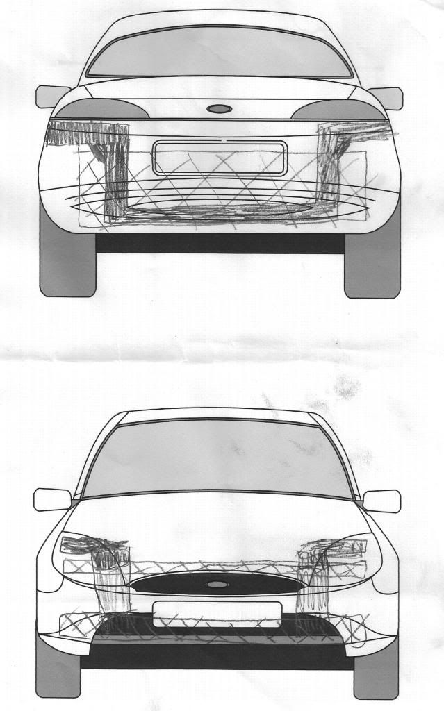
Will be a lot of work to get anywhere near a functioning design but will get there eventually.
 
thats a big project is that, why not go all out and design your own bodywork for it as well?

will you be going rear or 4wd?
 
I will use any track width i find is best for the wheelbase from a handling perspective. Aim to have it contained within S1600 bodywork width though. The joy of double wishbone is you can tweak all that dead easily. Make all your ball joints fully adjustable with generous thread length and you can do on the car track adjustments fairly freely and if you want more, make longer wishbones etc.

I dont fancy designing bodywork from scratch!! im no pinifirina or enzo ferrari in the design categories!! So will be keeping it based on the puma profile.

In theory there is no reason why the chassis could not have other body designs put on it though.
 
hmm i could do with a couple of those, this is going to be a very interesting build to watch evolve, you could potentially build the ultimate puma
 
The books are cheap enough on amazon to be fair.

Well technically it wouldnt be a puma anymore. It would be registered as a kit car sharing only bodywork and glass with a puma.

Well hopefully it will be a long while of designing, then the build of the basic chassis should be fairly quick.

I dont think it will be quite the ultimate puma, the gould car probably is that and i dont have a £100k budget!!!

Although i do have lots and lots of carbon in stock lol.
 
There was an article in fast ford with a carbon puma a while back..

610.jpg


http://nur-motorsport.co.uk/index.php/news/fordpuma/" onclick="window.open(this.href);return false;
 
Done a bit of research and a lot of monococque tubs are using a fairly simple skin based around either a 10mm foam core panel or 10mm honeycomb increasing to 15mm in some areas. Obciously the higher the level of motorsport, generally the more technical the core - ie slightly stiffer but lighter yet twice the cost!!

Some of the bigger sports cars use double skins formed into a box type section.

Also in a lot of the carbon cars they make use of honeycomb to form crash structures for frontal impact.

So with a bit of discussion with work colleagues ive come up with a sketch of my sill structure:
sillsketch.jpg


The outersill is original body panels remade in carbon with the void filled with honeycomb as a crash structure. It is not part of the monococque but represents the bodywork and in effect a replacement crash structure for minor accidents.

Ive chosen to use foam core. Its cheaper than alloy honeycomb and easier to produce a consistant strong panel (consistancy is important when you consider how much panel i will need!) and the only penalty being a 20% weight increase over honeycomb cores.

Plus its much easier and cheaper to make. The core isnt massively more expensive if you use honeycomb, however the specialist glue film sheeting, which needs oven curing, IS expensive and could easily add a couple of grand to the cost of a monococque.

I also intend to fill the monococque side panel voiding with honeycomb. It will add some stiffness plus add further crash protection with the honeycomb absorbing energy as it crushes.

Should give me a good strong side profile.
 
the nur motorsport puma is pretty impressive but as warren says its only carbon panels.

the gould car is still a puma chassis right? or is it space framed?
 
bit of an update.

Been slowly learning CAD to get my design shape down roughly.

So its time to test some materials! I'm looking at either using a 20mm or 10mm foam or alloy honeycomb core material with carbon either side.

So this was a practical but not extremely scientific test of a sample panel i have made. This panel was made of 2mm carbon fibre, 20mm aluminium honeycomb and another 2mm of carbon.

I expected it to be a massive overkill from other carbon tubs ive seen, but Ive done it for a bench mark.

First of all put it between bricks and got me and my mate to jump on it - no visible damage and no visible deflection while loaded.

so i thought "fuck it" and decided to run it over with my 4x4 bear in mind the weight distribution is such that the front wheel i used was loaded to about 500kg spread over the tyre contact patch.

The test piece is 50cm by 30cm.

Test one - simple drive on it:
20131007_184310.jpg

no measurable deflection and no visible damage afterwards.

Time to up the anti.....

Prop it on a brick against the kerb, and drive onto it like a ramp:
20131007_184651.jpg

about 3-5mm measurable elastic deflection. No structural damages except minor gouges on surface of carbon where it rested on the brick and ground.

So up anti again and just rest on the kerb:
20131007_184831.jpg

Almost identical results to above.

Proof it is a heavy 4x4 and not a mini:
20131007_184845.jpg


The final test, put it between 2 bricks and drop off the kerb heavily. See how it does with a bit pf shock loading!!
20131007_185034.jpg

The defelection was permenant this time with the shock loading! No obvious cracking in the carbon but the honeycomb does appear crushed in places.

Although not massively scientific, has confirmed that a 20mm core is overkill for the main parts of the chassis and 10mm is likely to be plenty. 20mm will be reserved for the high loading members.
 
If you performed the same test with a 3mm piece of mild steel (the thickest that you'll fix on a puma), it would have buckled instantly!
 
Yes, something like this isn't something one just throws togehter in a shed :) it takes a great deal of planing and design to make it both safe, and usable... :)

But my, what an awsome machine it wil be :)
 
This is some project - Books look interesting too. I might have to get the aerodynamics one!

It's going to be awesome to see the real product.
 
Back
Top