warrenpenalver
Active member
yes another lunatic is looking to make a new inlet!
Now i dont have a Zetec SE engined puma, but i am soon starting to build a Zetec SE for my KA.
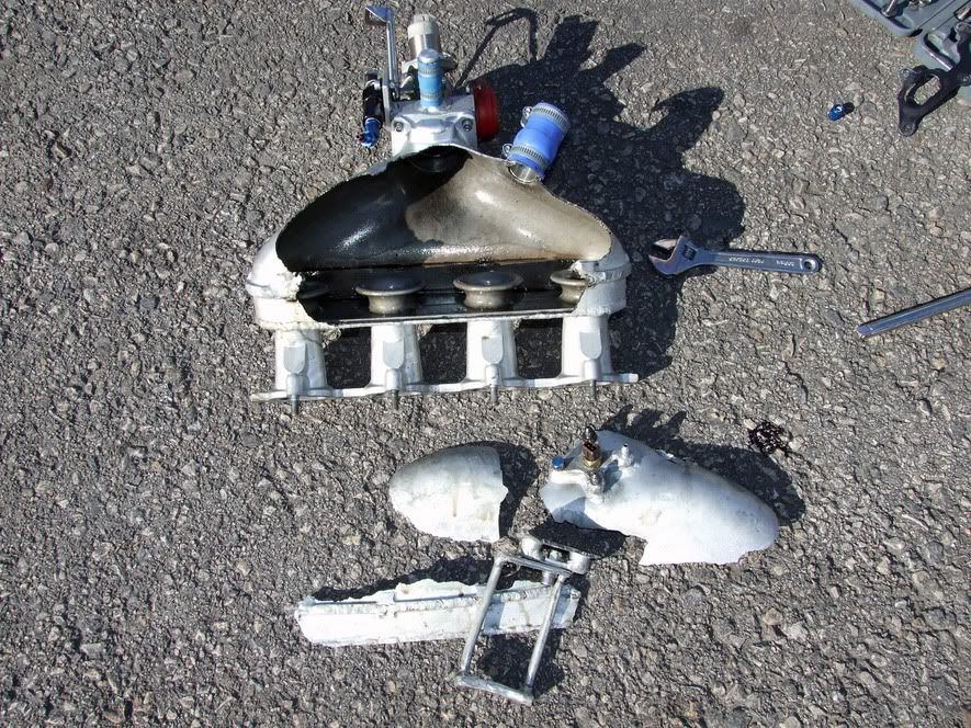
What i am doing is to make a large log type plenum to withstand turbo boost. Initially i am going to use the mounting method seen on the LMS inlet, ie mount the plenum chamber to the upper part of the inlet.
That should be fairly simple to do and make.
Secondly i am looking at a compact inlet manifold in carbon. On the KA the engine bay curves down sharply further back than in the puma, so a FRP inlet is too high to clear the bonnet, and a lms style inlet needs the cross member hacked apart.
I will custom route the tubes so i can bring the plenum chamber a bit lower and closer to the engine while just clearing the alternator.
With my work, i already have a mould i can borrow for a massive plenum chamber, so half the work is done. This is what the plenum will look like:

I just need to make a baseplate for it to mount to the inlet and a flange for the throttle body end. This plenum has a 100MM intake so plenty of space for people to fit a bigger throttle body if ever needed.
Now i dont have a Zetec SE engined puma, but i am soon starting to build a Zetec SE for my KA.
What i am doing is to make a large log type plenum to withstand turbo boost. Initially i am going to use the mounting method seen on the LMS inlet, ie mount the plenum chamber to the upper part of the inlet.
That should be fairly simple to do and make.
Secondly i am looking at a compact inlet manifold in carbon. On the KA the engine bay curves down sharply further back than in the puma, so a FRP inlet is too high to clear the bonnet, and a lms style inlet needs the cross member hacked apart.
I will custom route the tubes so i can bring the plenum chamber a bit lower and closer to the engine while just clearing the alternator.
With my work, i already have a mould i can borrow for a massive plenum chamber, so half the work is done. This is what the plenum will look like:
I just need to make a baseplate for it to mount to the inlet and a flange for the throttle body end. This plenum has a 100MM intake so plenty of space for people to fit a bigger throttle body if ever needed.